Double-rotor gravity machine technology
A dual-rotor, gravity technology, applied in the direction of engines, mechanical equipment, machines/engines, etc., can solve the problems of secondary pollution of electricity storage, unstable power generation, and high power generation costs
- Summary
- Abstract
- Description
- Claims
- Application Information
AI Technical Summary
Problems solved by technology
Method used
Image

Examples
Embodiment 1
[0058] Example 1 , inner rail gravity machine (see attached Figure 11 and 15 ).
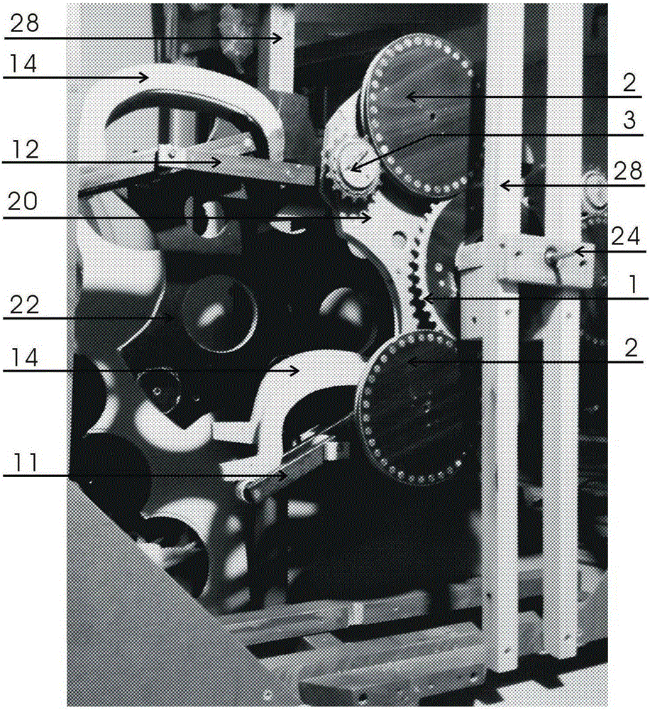
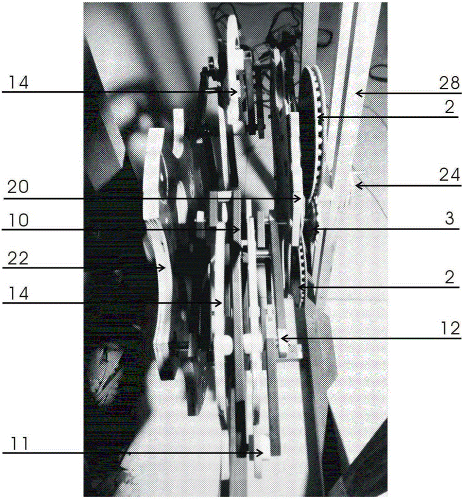
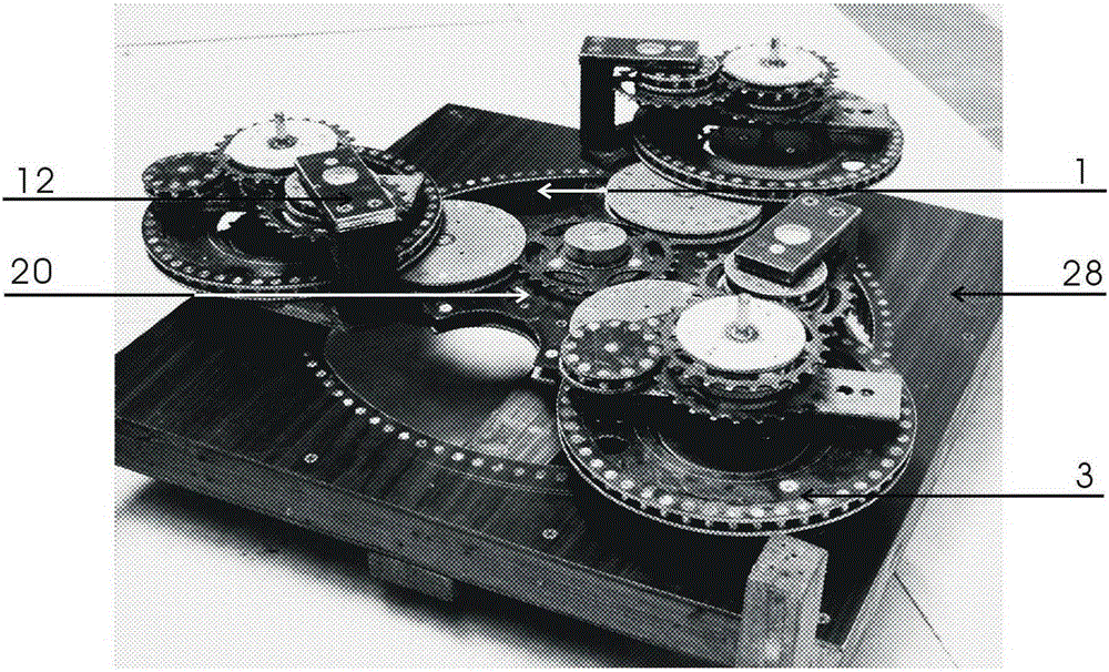
[0059] Main work system: A rotor (20) is tightly fitted on the rotor shaft, the rotor shaft is mounted on the frame (28) with bearings, the power take-off wheel (27) is installed on the rotor shaft outside the frame (28), the main The control fixed gear (1) is fixed on the frame (28) concentrically with the rotor shaft, and the three sets of transmission gears (2) are respectively mounted on the rotor arm (21) on the back of the A rotor (20) with bearings and are connected with the main control fixed gear. (1) Meshing; both ends of the main crankshaft (10) are mounted on the A.B rotor connection frame (12) with bearings, and one end of the central shaft of the main crankshaft (10) is mounted on the A rotor arm (21) with bearings. The three main work The gear (3) and the passive synchronizing gear (6) are concentrically and tightly fitted on the central shaft of the main crankshaft (10) on t...
Embodiment 2
[0062] Example 2 , outer rail gravity machine (see attached Figure 12 , refer to appendix Figure 16 ).
[0063] Main work system: A rotor (20) is tightly fitted on the rotor shaft, the rotor shaft is mounted on the frame (28) with bearings, and the power take-off wheel (27) is installed on the rotor shaft outside the frame (28). The control fixed ring gear (1b) is fixed on the frame (28) concentrically with the rotor shaft; the main work gear (3) is mounted on the A rotor arm (21) with a bearing and meshes with the main control fixed gear ring (1b); The central shafts at both ends of the crankshaft (10) are respectively mounted on the A.B rotor connecting frame (12) with bearings, one end of the central shaft of the main crankshaft (10) is mounted on the A rotor arm (21) with bearings, and the other end is mounted on the B rotor with bearings. On the arm (23), the three main power driving gears (3-1) and the passive synchronizing gears (6) are installed on the central s...
Embodiment 3
[0066] Example 3 , multi-rail gravity machine A (see appendix Figure 13 , refer to appendix Figure 16 ).
[0067] Primary work and main work system: The main control fixed gear L (1a) is respectively fixed on the three rotor arms (21) of the A rotor (20), the rotor shaft is tightly fitted on the A rotor (20), and the A rotor shaft is installed on the A rotor (20). (24) The bearing is installed on the frame (28), the power output wheel (27) is tightly installed on the rotor shaft outside the frame (28); the two ends of the central shaft of the main crankshaft (10) are respectively installed on the A.B rotor with bearings On the connecting frame (12), the long end of the central axis of the main crankshaft (10) is mounted on the A rotor arm (21) with a bearing, and the main working gear (3) and the passive synchronizing gear (6) are tightly mounted on the main crankshaft (10) On the center of one side of the A rotor (20); the weight 3 (19) is fixed on the gravity displace...
PUM
 Abstract
Description
Claims
Application Information
 - R&D
- Intellectual Property
- Life Sciences
- Materials
- Tech Scout
- Unparalleled Data Quality
- Higher Quality Content
- 60% Fewer Hallucinations
Browse by: Latest US Patents, China's latest patents, Technical Efficacy Thesaurus, Application Domain, Technology Topic, Popular Technical Reports.
© 2025 PatSnap. All rights reserved.Legal|Privacy policy|Modern Slavery Act Transparency Statement|Sitemap|About US| Contact US: help@patsnap.com