
Flatness and inclination optical measurement method

A technology of optical measurement and flatness, applied in the field of optical measurement, can solve the problems of expensive equipment, narrow use range, low efficiency, etc., and achieve the effects of reduced measurement difficulty, wide application range and huge application value

Inactive Publication Date: 2016-12-21
欧阳一平
View PDF8 Cites 21 Cited by
  • Summary
  • Abstract
  • Description
  • Claims
  • Application Information

AI Technical Summary

Problems solved by technology

Most of the contact methods cannot measure some difficult-to-reach positions, the scope of use is narrow, and the description of flatness and inclination is not comprehensive and intuitive; most non-contact methods use optical technology, and currently there are mainly space restrictions on the measured object, equipment Expensive and other issues
Various problems exist in the current non-contact measurement methods, so far, the measurement of flatness and inclination in many fields has relied on some of the most primitive manual operation methods in the contact method, which is very inefficient and unsatisfactory.

Method used


Image

  • Flatness and inclination optical measurement method
  • Flatness and inclination optical measurement method
  • Flatness and inclination optical measurement method

Examples


Embodiment Construction

[0037] In order to make the purpose, technical solution and advantages of the invention clearer, the present invention will be further described in detail below in conjunction with the accompanying drawings and examples. It should be understood that the specific implementation examples described here are only used to explain the present invention, not to limit the present invention.

[0038] First of all, it is stated that the present invention is mainly applicable to approximate planes with small undulations, and excessive undulations of the measured surface will reduce the measurement accuracy.

[0039] The whole set of measuring equipment includes a laser rangefinder, one or two planar laser emitters of different colors, a digital camera, and a computer.

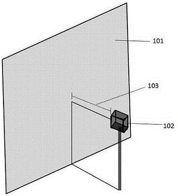
[0040] First, an example of measuring a vertical plane will be described. Such as figure 1 As shown, the planar laser generator in the device will be measured ( figure 1 middle 102) placed on the surface to be tested C...


PUM


Abstract

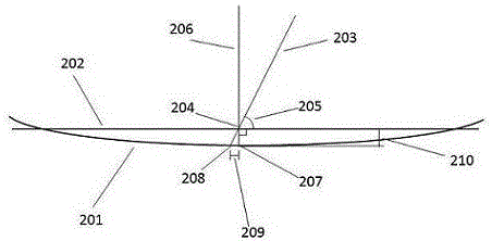
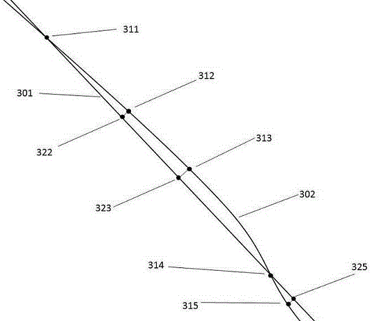
The invention discloses a method for measuring approximate plane flatness and inclination by using optical technology. First artificially define a standard plane that is close to the actual measured plane, and place a planar laser generator at a certain distance from the standard plane, so that there is a non-90° angle between the laser plane and the standard mathematical plane, then There will be a linear area illuminated by the laser on the measured surface. According to the difference between the projection of the area and the intersection line between the laser plane and the standard mathematical plane on the measured surface, the corresponding position relative to the The bump gap value for the standard plane. Take pictures of the measured surface irradiated by the laser through a digital camera, collect the data of these deviations, use a computer to analyze and calculate, and obtain the overall flatness data of the measured plane and the inclination relative to the standard plane. The invention provides a convenient, accurate, fast and low equipment cost method for measuring the flatness and inclination of various approximate planes.

Description

technical field [0001] The invention relates to the field of optical measurement, in particular to a method for optically measuring the flatness and inclination of various approximate planes. Background technique [0002] The measurement of the flatness and inclination of the approximate plane is a very widely distributed and very important task in various types of projects and industrial production, such as the flatness and inclination of road and bridge surfaces in road and bridge engineering Angle detection, detection of the flatness and inclination angle of the inner and outer walls of the building in construction, and the detection of product surface flatness in machinery manufacturing, etc. [0003] Currently, such work is carried out in different fields using various methods. [0004] In the field of road surface flatness measurement, there are currently two main types of methods: cross-section and reaction. The cross-section is essentially used to measure the uneven...

Claims


Application Information

Patent Timeline
IPC IPC(8): G01B11/30
CPCG01B11/30
Inventor 欧阳一平汤谨阳谢宇乘
Owner 欧阳一平
Learn More