
Multi-surface shape measurement method based on frequency blind estimation

A measurement method and multi-surface technology, applied in the direction of measuring devices, instruments, optical devices, etc., can solve the problems that the interferogram cannot obtain accurate results, cannot be separated, and cannot obtain accurate calculation results.

Active Publication Date: 2020-12-18
SHANGHAI UNIV
View PDF5 Cites 5 Cited by
  • Summary
  • Abstract
  • Description
  • Claims
  • Application Information

AI Technical Summary

Problems solved by technology

However, the limitations of these measurement methods are: for the hardware interferometer, the phase shift operation is performed by changing the local interference cavity length due to the piezoelectric ceramic driver. In this case, the phase shift frequency of each signal is the same and cannot be separated. , so in actual application, the method of successive measurement and surface coating with matting material is often used for measurement
The disadvantage of this method is that if the selected points are noisy or have defects on the surface, the entire set of interferograms will not get accurate results; and vice versa, if the selected representative points are not enough Information changes representing the distribution of the entire pixel point will still not achieve accurate calculation results
In addition, the difficulty of measuring the multi-surface lens lies in: in the process of collecting the interferogram of the tested object, since the distances between each plane and the reference mirror are different, when using the wavelength phase-shifting interferometer for phase-shifting operation, the The phase change of each interference signal is different, that is, each interference signal has a different phase shift frequency, which is one of the basis for signal separation
Therefore, in the interferogram, each signal will be aliased in the collected data, so that the interferogram of signal aliasing cannot be directly solved

Method used


Image

  • Multi-surface shape measurement method based on frequency blind estimation
  • Multi-surface shape measurement method based on frequency blind estimation
  • Multi-surface shape measurement method based on frequency blind estimation

Examples


Embodiment 1

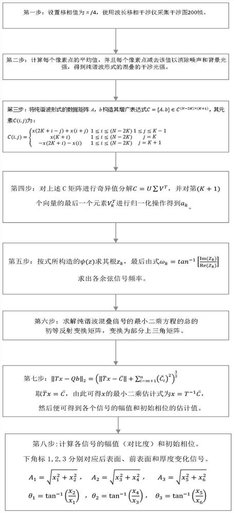
[0085] In this example, see figure 1, a multi-surface surface shape measurement method based on frequency blind estimation, through the blind estimation of the interference frequency of each point in the collected interferogram and the solution of the amplitude and phase, the one-time measurement of the measured object with multiple surfaces is completed Non-contact measurement; using a wavelength phase-shifting interferometer to collect the interferogram of the measured object, the multi-surface surface measurement method based on frequency blind estimation includes the following steps:

[0086] a. Carry out blind frequency estimation based on the independent distribution of the interference frequency of each signal on the light intensity change fringe pattern of the superimposed cosine signal, so as to determine the precise frequency distribution of each interference signal;

[0087] b. Calculate through the new least squares initial phase and amplitude solution method to re...

Embodiment 2

[0090] This embodiment is basically the same as Embodiment 1, especially in that:

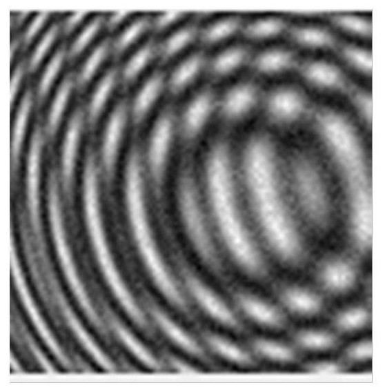
[0091] In this example, see figure 1 , when solving the interference frequency of each signal, consider the interferogram superimposed by the front and rear surfaces and thickness changes. According to the laser propagation characteristics, the collected fringe pattern is expressed as the superposition of three groups of cosine signals. Expressed as a signal composed of K cosine signals and noise e(n) superimposed, written as the following expression:

[0092]

[0093] In the formula, the ordinal numbers of the actual collected data are n=1,...,N,{A k , ω k : k=1,...K} is the unknown real quantity, θ k : k=1,...N is an independent random variable between -π~π, has a uniform distribution characteristic, and corresponds to the initial phase of each signal; ω k is the frequency of each signal; A k is the contrast of each signal; the blind frequency estimation is obtained from the given N ...

Embodiment 3

[0147] This embodiment is basically the same as Embodiment 2, and the special features are:

[0148] In this example, see Figure 1-7 , considering that when the wavelength is phase shifted, different surfaces correspond to different interference signal phase shift frequencies, and from the time domain signal frequency, the collected interference fringe pattern is equivalent to the superposition of multiple sets of cosine signals. Therefore, multiple groups of signals can be separated based on different phase shifting frequencies, so as to extract different surface shape information. This can eliminate the influence of the cavity length that cannot be satisfied when the DUT is placed. The method proposed in this embodiment mainly includes two parts:

[0149] (1) Carry out blind frequency estimation based on the independent distribution of the interference frequency of each signal on the light intensity variation fringe pattern of the superimposed cosine signal, so as to dete...


PUM


Abstract

The invention discloses a multi-surface shape measurement method based on frequency blind estimation, which comprises the following steps of: acquiring an interferogram by using a wavelength phase-shifting interferometer, and accurately solving and matching corresponding signal frequency characteristics through blind estimation of each surface interference frequency in the multi-surface interferogram; and substituting the solved interference frequency of each signal into the constructed novel least square solving equation to solve the amplitude and initial phase of each interference signal ofthe measured piece, thereby completing the multi-surface interference measurement of the transparent parallel plate. The measurement method is low in cost, avoids measurement of the average thicknessof the measured piece, and can accurately solve the contrast of each surface of the measured piece.

Description

technical field [0001] The invention relates to a multi-surface surface shape measurement method based on interference frequency blind estimation, in particular to obtain the interference frequency of each signal through the blind separation method, and then obtain the initial phase through a new least square method to reconstruct the multi-surface shape Measurement methods. The invention realizes the blind separation and reconstruction of the interference signal through the accurate solution of the frequency and phase of each surface signal. Background technique [0002] High-precision multi-surface parallel plates play an important role in the construction of optical systems. Among them, the accurate surface measurement and reconstruction of the multi-surface lens has practical significance and research value for the improvement and evaluation of the imaging and transmission quality of the optical system, and is one of the research hotspots in the field. [0003] Traditi...

Claims


Application Information

Patent Timeline
IPC IPC(8): G01B11/24
CPCG01B11/2441
Inventor 常林郑维伟于瀛洁闫恪涛徐瞿磊孙涛王陈
Owner SHANGHAI UNIV
Learn More