Efficient and convenient and quick simple robot calibrating method

A calibration method and robot technology, applied in manipulators, program-controlled manipulators, manufacturing tools, etc., can solve the problems of poor practicability and convenience of zero-position calibration, low robot control accuracy, and complicated processes, so as to reduce the cost of measurement equipment, Improve usability and convenience, measure simple effects

Active Publication Date: 2018-02-23
CHENGDU CRP ROBOT TECH CO LTD
View PDF5 Cites 23 Cited by
  • Summary
  • Abstract
  • Description
  • Claims
  • Application Information

AI Technical Summary

Problems solved by technology

[0003] The purpose of the present invention is: the present invention provides an efficient and convenient simple robot calibration method, which solves the problem of poor practicability and convenience of zero calibration due to the complicated process and high cost of the existing zero calibration using a calibration instrument and software combination method, As a result, the problem of low control precision of the robot has been achieved, and the effect of pure software to achieve zero calibration and improve practicability to achieve precise control

Method used


Image

  • Efficient and convenient and quick simple robot calibrating method
  • Efficient and convenient and quick simple robot calibrating method
  • Efficient and convenient and quick simple robot calibrating method

Examples


Embodiment 1

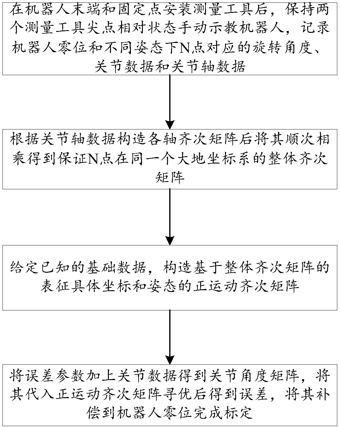
[0037] An efficient and convenient simple robot calibration method, comprising the following steps:

[0038] Step 1: After installing the measuring tool at the end of the robot and the fixed point, keep the sharp points of the two measuring tools facing each other and teach the robot manually, and record the robot zero position and the rotation angle, joint data and joint axis data corresponding to the N point in different postures;

[0039] Step 1 includes the following steps:

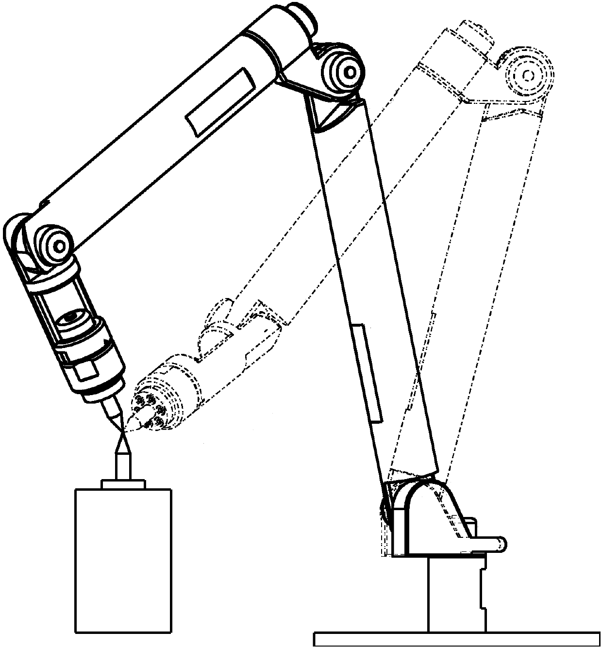
[0040] Step 1.1: Install measuring tool 1 on the end flange of the robot, and install measuring tool 2 at a fixed point within the robot’s motion range;

[0041] Step 1.2: Always keep the cusp of measuring tool 1 and measuring tool 2 facing each other, manually teach the robot, and record the robot zero position and the rotation angle, joint data and joint axis data corresponding to point N in different postures.

[0042] Step 2: Construct the homogeneous matrix of each axis according to the joint ax...

Embodiment 2

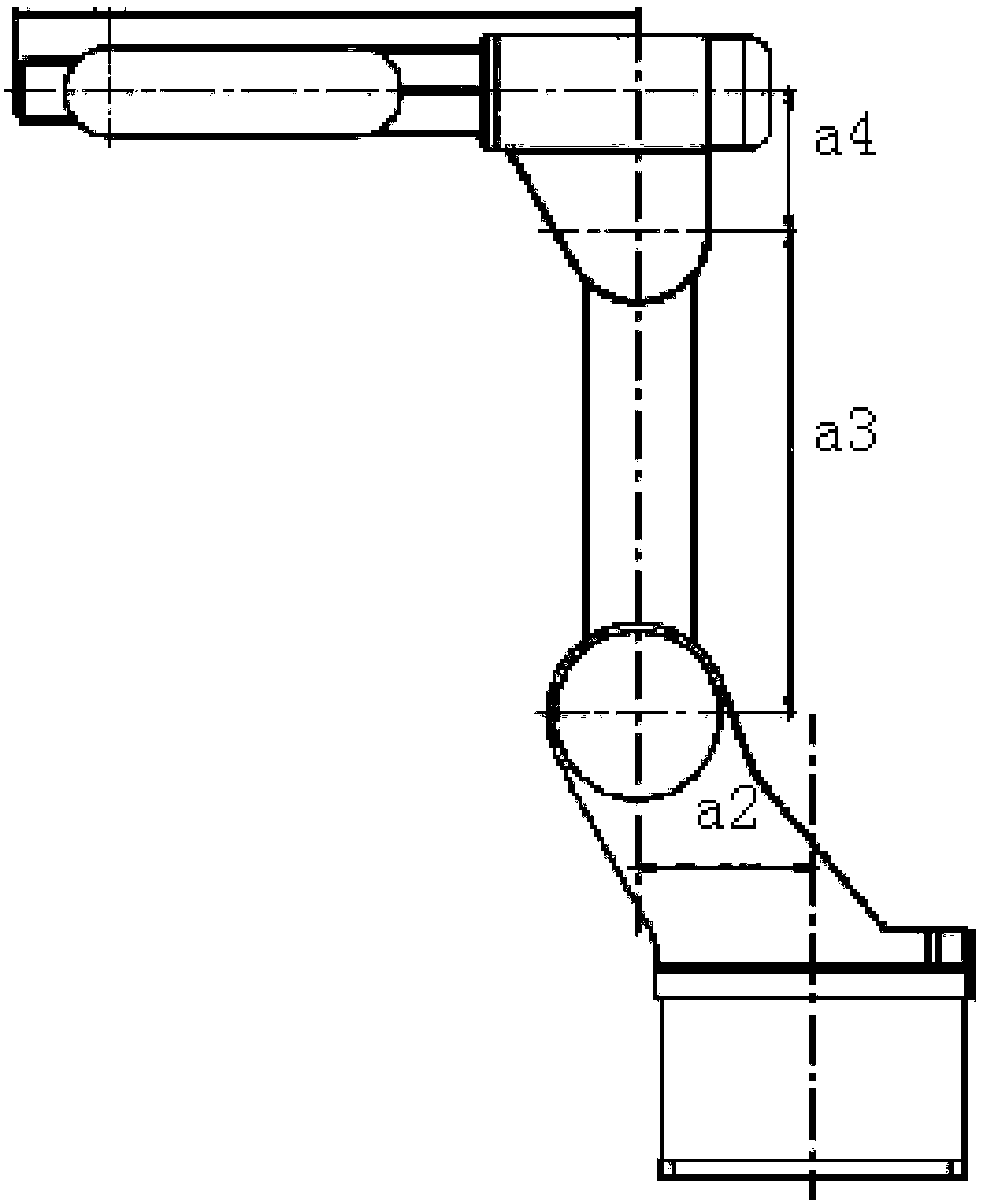
[0058] Take a robot with six degrees of freedom as an example:

[0059]Step 1: Install measurement tool 1 on the end flange of the robot, and install measurement tool 2 at a fixed point within the robot’s motion range; always keep the sharp point of measurement tool 1 and measurement tool 2 facing each other, and manually teach the robot to obtain different postures The rotation angle θ corresponding to the next 20 points 1 ,θ 2 ,θ 3 ,θ 4 ,θ 5 ,θ 6 , joint data and joint axis data f(θ 1 ,θ 2 ,θ 3 ,θ 4 ,θ 5 ,θ 6 ) and record the zero value;

[0060] Step 2: Construct a homogeneous matrix for each axis, such as 1 axis for Abbreviation for joint J 1 Coordinate system rotation θ 1 The homogeneous coordinate system matrix relative to the Cartesian coordinate system after degrees, where [r 11 r 12 r 13 ] represents the vector of the x-axis of the coordinate system relative to the earth coordinate system, [r 21 r 22 r 23 ] represents the vector of the y...


PUM


Abstract

The invention discloses an efficient and convenient and quick simple robot calibrating method, and relates to the field of robot zero position calibration. The robot calibrating method comprises the following steps that 1) keeping cuspidal points of measuring tools opposite all the time after the mounting is completed, manually teaching a robot, and recording corresponding joint data and joint axis data of N points; 2) constructing homogeneous matrices of various axes according to the joint axis data, and then multiplying the homogeneous matrices in sequence, thus obtaining an overall homogeneous matrix; 3) giving basic data, and constructing a positive movement homogeneous matrix based on the overall homogeneous matrix; and 4) adding the joint data to a given error parameter, thus obtaining a joint angle matrix, and substituting the joint angle matrix in the positive movement homogeneous matrix for optimizing, thus obtaining an error, and then compensating the error to a robot zero position, thus completing the calibration. The problem that the robot control precision is low due to the fact that a calibration instrument and software combined process adopted for existing zero position calibration is complicated in procedure and high in cost and the zero position calibration practicability of a calibration instrument and software is poor is solved, and the effects that zero position calibration by pure software is realized, the practicability is improved and precision control is realized are achieved.

Description

technical field [0001] The invention relates to the field of robot zero calibration, in particular to an efficient and convenient simple robot calibration method. Background technique [0002] Since the motion of each axis of the joint robot is a rotational motion, to make the end perform a linear motion or run a specific trajectory in a certain coordinate system, the coordinate conversion of the rotary joint and the linear motion must be carried out; the rotational motion is converted into a linear motion as the forward motion of the robot The linear motion is transformed into joint motion to solve the inverse kinematics of the robot; when the control algorithm design is completed, the end value of the robot's current joint and the joint value under the current end value can be obtained in real time; if the theoretical algorithm is required for the actual body Control needs to ensure three parameters that affect the accuracy of the end position of the robot. The three param...

Claims


Application Information

Patent Timeline
Patent Type & Authority Applications(China)
IPC IPC(8): B25J9/16B25J19/00
CPCB25J9/1692B25J19/0095
Inventor 谷菲朱路生
Owner CHENGDU CRP ROBOT TECH CO LTD
Why Eureka
Try Eureka