Low-profile broadband ultrahigh-frequency radio frequency identification antenna

A radio frequency identification, low profile technology, applied in the field of radio frequency identification, can solve the problems of deviation between actual measurement and simulation, large volume unfavorable installation, complex antenna structure, etc., to achieve the effect of low profile height, simple structure and small volume

Active Publication Date: 2016-12-21
XIDIAN UNIV
View PDF6 Cites 2 Cited by
  • Summary
  • Abstract
  • Description
  • Claims
  • Application Information

AI Technical Summary

Problems solved by technology

[0003] The purpose of the present invention is to provide a low-profile broadband ultra-high frequency radio frequency identification antenna, which aims to solve the problems of high antenna profile, large volume, narrow bandwidth, and complex structure. The high profile and large volume are not conducive to installation; as an antenna in the field of radio frequency identification The antenna has a narrow bandwidth, and a single antenna cannot be used to identify tags in the entire RFID frequency band; the complex structure of the antenna is not conducive to processing, resulting in processing errors that do not match the simulation, and deviations between actual measurement and simulation.

Method used


Image

  • Low-profile broadband ultrahigh-frequency radio frequency identification antenna
  • Low-profile broadband ultrahigh-frequency radio frequency identification antenna
  • Low-profile broadband ultrahigh-frequency radio frequency identification antenna

Examples


Embodiment Construction

[0023] In order to make the objectives, technical solutions and advantages of the present invention clearer, the present invention will be further described in detail below with reference to the embodiments. It should be understood that the specific embodiments described herein are only used to explain the present invention, but not to limit the present invention.

[0024] The structure of the present invention will be described in detail below with reference to the accompanying drawings.

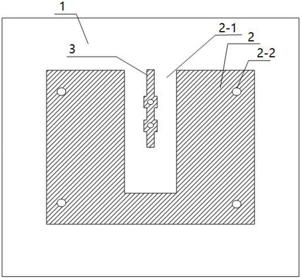
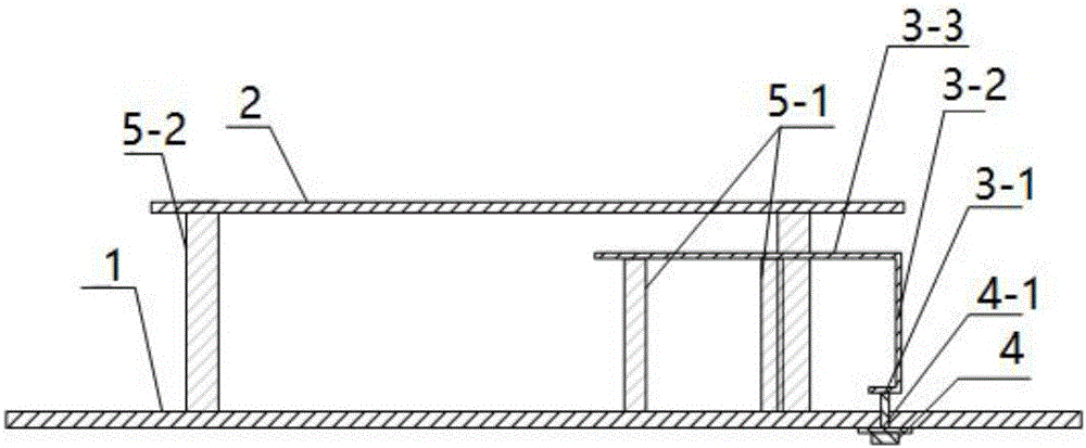
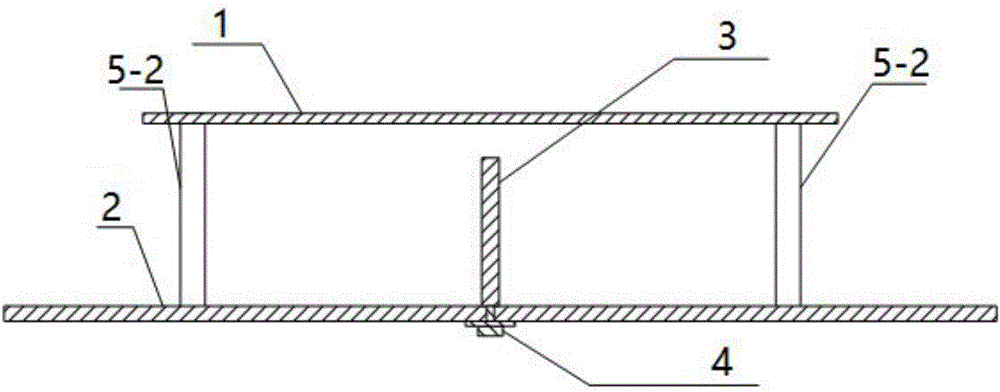
[0025] like figure 1 , 2, 3, the low-profile broadband UHF RFID antenna of the embodiment of the present invention includes a metal ground plate 1, a metal radiating plate 2, a rotating г-shaped metal strip 3, an SMA connector 4, and 6 dielectric columns 5.

[0026] Two supporting metal strip dielectric columns 5-1 supporting the metal strip, four supporting metal radiating plate dielectric columns 5-2 supporting the metal radiating plate, the metal radiating plate 2 is placed directly abo...


PUM


Abstract

The invention discloses a low-profile broadband ultrahigh-frequency radio frequency identification antenna. The low-profile broadband ultrahigh-frequency radio frequency identification antenna is provided with a metal grounding plate, a metal radiation plate and an SMA joint; the SMA joint is arranged on the metal grounding plate below a rotation downwards-inversed-L-shaped metal band; the SMA joint is located in the projection of the metal radiation plate on the metal grounding plate; a rectangular slot is formed at one edge of the metal radiation plate; the rotation downwards-inversed-L-shaped metal band is located at the center of the rectangular slot; and one end of the rotation downwards-inversed-L-shaped metal band is connected with the SMA joint. Compared with the prior art, and according to the antenna of the invention, the height of the profile of the antenna is reduced to about 0.08Lambda, so that the antenna can be broadband; the rectangular metal radiation sheet is adopted, and the side edge of the rectangular metal radiation sheet is slotted, and therefore, the linear polarization bandwidth of the antenna can be still large when S11 is smaller than -15dB; and the rotation 90-degree downwards-inversed-L-shaped bent metal band is adopted as a feeder line, and coupling feeding is carried on two sides of the slit of the metal radiation plate with the rectangular slot based on an air dielectric. Compared with an existing ultrahigh-frequency antenna, the low-profile broadband ultrahigh-frequency radio frequency identification antenna of the invention has wider bandwidth.

Description

technical field [0001] The invention belongs to the technical field of radio frequency identification, and in particular relates to a low-profile broadband linearly polarized antenna applied to an ultra-high frequency radio frequency identification system. Background technique [0002] Radio frequency identification (RFID) technology wireless identification and tracking capabilities originated in World War II. In recent years, radio frequency identification technology has received more and more attention and has been applied to various industries such as logistics, retail, industrial production, etc. A complete radio frequency identification system consists of tags, readers, and a computer control terminal. After the tag enters the magnetic field, the receiving reader transmits a radio frequency signal of a specific frequency to the tag, that is, the transponder, to drive the transponder circuit to send the internal data. At this time, the reader receives and interprets the...

Claims


Application Information

Patent Timeline
Patent Type & Authority Applications(China)
IPC IPC(8): H01Q1/22H01Q1/36H01Q1/48H01Q1/50
CPCH01Q1/2216H01Q1/36H01Q1/48H01Q1/50
Inventor 王紫阳尹应增杨赵
Owner XIDIAN UNIV
Why Eureka
Try Eureka