Eureka AIR delivers breakthrough ideas for toughest innovation challenges, trusted by R&D personnel around the world.

Direct-pull separated connector

A connector and detachable technology, applied in the direction of connection, parts of connecting devices, devices for connecting/disconnecting connecting parts, etc., can solve problems such as large pulling force, and achieve the effect of easy unlocking

Active Publication Date: 2016-12-21
CHINA AVIATION OPTICAL-ELECTRICAL TECH CO LTD
View PDF6 Cites 0 Cited by
  • Summary
  • Abstract
  • Description
  • Claims
  • Application Information

AI Technical Summary

Problems solved by technology

[0003] The purpose of the present invention is to provide a straight-pull separation connector, which aims to solve the problem of excessive pulling force required in the prior art for the separation process of the connector

Method used


Image

  • Direct-pull separated connector
  • Direct-pull separated connector
  • Direct-pull separated connector

Examples


Embodiment Construction

[0025] Embodiment of the pull-cord drop-off connector in the present invention: the connector is a screw-connected straight-pull separation plug with a built-in drive. Under the action of the mechanism, the separation force of the plug is greatly reduced, and the separation force is stable and controllable.

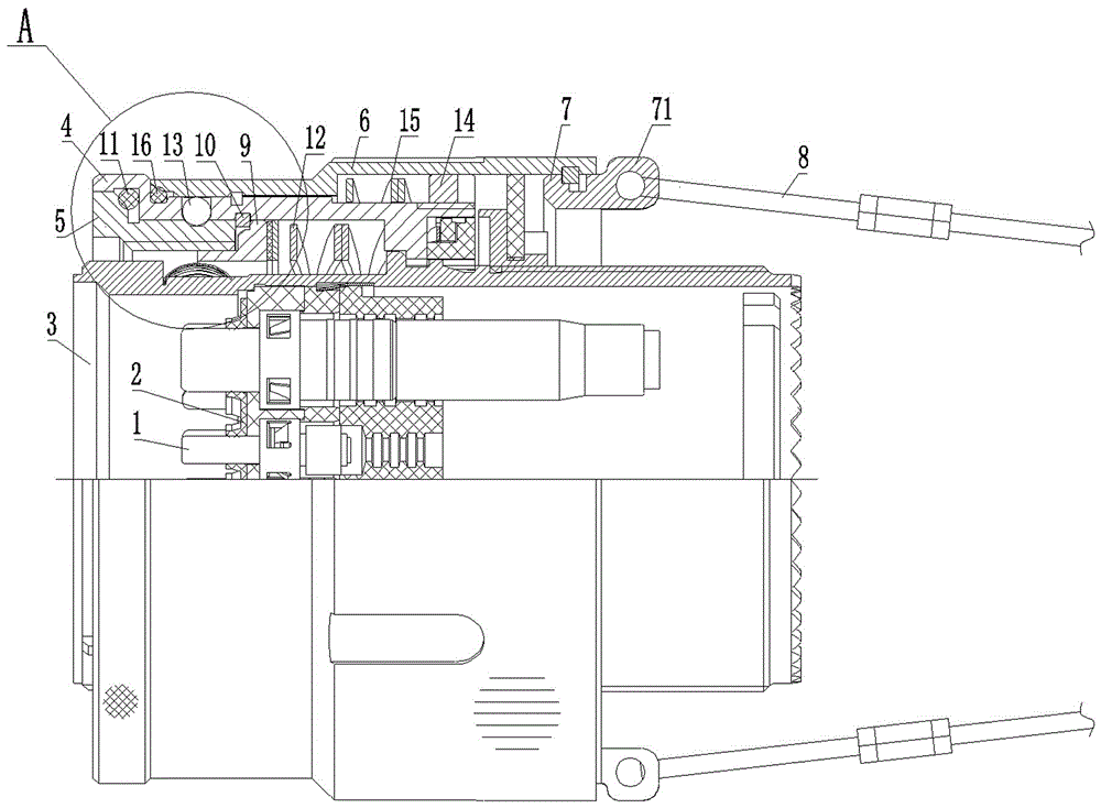
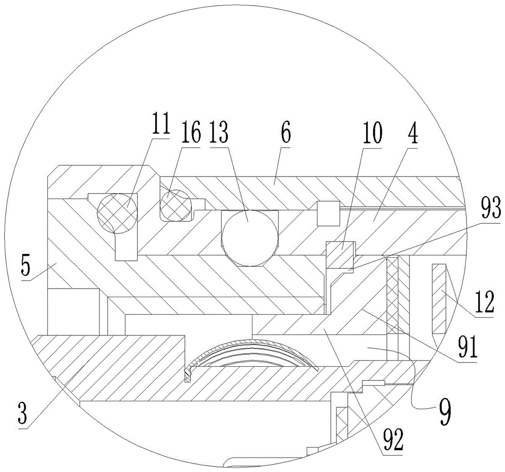
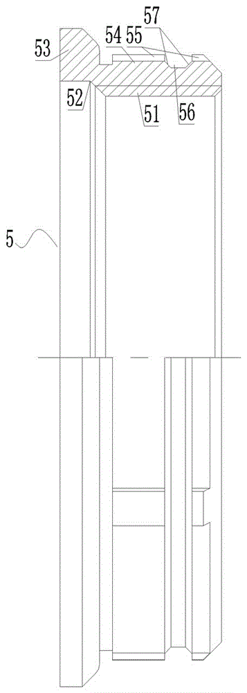
[0026] Such as figure 1 and figure 2 As shown, the plug includes a plug part. The plug part is composed of a contact piece 1, an insulator 2 and a plug shell 3. The contact piece 1 is assembled in the plug shell 3 through the insulator 2, and the plug shell 3 is covered with an axial stopper. Assembled swivel sleeve 4, the swivel sleeve 4 is connected with the threaded sleeve 5 through the inner keyway structure, and the pull-off housing 6 is set on the outside of the swivel sleeve 4 through the outer keyway structure, and the rear end of the pull-off housing 6 is equipped with a rear limiter The pull ring 7 is provided with two symmetrically arranged pull ears 71 on t...


PUM


Abstract

The invention discloses a direct-pull separated connector. The direct-pull separated connector comprises a connector shell and a thread bushing, wherein the thread bushing sleeves the connector shell, a pull disconnection shell is arranged outside the thread bushing, an internal thread is arranged on an inner wall of the thread bushing, an insertion space is arranged between an internal thread segment of the thread bushing and the periphery of the connector shell and is used for a front end of an adaptive connector to insert, a front end of the insertion space is an opening for the front end of the adaptive connector to enter, a rear end of the insertion space is equipped with a top ring, the top ring is provided with a sleeve body segment, the sleeve body segment can move forwards and backwards and is inserted between the thread bushing and the connector shell, a front end of the sleeve body segment is a top push end, the top push end is arranged in front of a rear end of the internal thread segment, and an unlocking spring is connected with the top ring and is used for forwards propping against the top ring. During the process of pulling the pull disconnection shell for unlocking, the unlocking spring will push the front end of the adaptive connector by the top push end of the top ring with unlocking of the thread bushing, an elastic push force belongs to an assistant force of pulling and unlocking, and thus, a pull force required for pulling the connector is reduced.

Description

technical field [0001] The invention relates to a straight-pull separation connector. Background technique [0002] The traditional standard interface pull cord release connector adopts an open threaded sleeve structure to realize thread locking and straight pull separation with the socket. For example, the pull-off connector disclosed in Chinese patent document CN 102544883 B includes a connector housing with a built-in pin part, and a pull-off housing with a rear limit sliding assembly on the outside of the connector housing, and the pull-off housing and The return spring that drives the pull-off housing to move forward and the open threaded sleeve located at the front of the connector housing are installed between the connector shells. The open threaded sleeve is axially fixed on the connector shell. It has an internal thread that cooperates and locks with the external thread at the front end of the adapter connector. The front section of the split threaded sleeve is als...

Claims


Application Information

Patent Timeline
Patent Type & Authority Applications(China)
IPC IPC(8): H01R13/635H01R13/622
CPCH01R13/622H01R13/635
Inventor 庞卓陈继利卞书波康萌金同顺
Owner CHINA AVIATION OPTICAL-ELECTRICAL TECH CO LTD
Why Eureka
Eureka Blog
Learn More