a lifting table

A technology of lifting table and lifting frame, applied in the field of lifting table, can solve the problems of unstable lifting process and laborious lifting, and achieve the effect of stable lifting process and improving user experience.

Active Publication Date: 2020-04-28
深圳米乔人因科技有限公司
View PDF7 Cites 0 Cited by
  • Summary
  • Abstract
  • Description
  • Claims
  • Application Information

AI Technical Summary

Problems solved by technology

[0007] The purpose of the present invention is to provide a lifting table capable of adjusting the lifting power, which allows users to adjust the lifting power according to the load of the lifting table, and solves the problem that the lifting process of the existing lifting table is not stable and the lifting process is not stable due to the different loads of the table. strenuous problem

Method used


Image

  • a lifting table
  • a lifting table
  • a lifting table

Examples


Embodiment 1

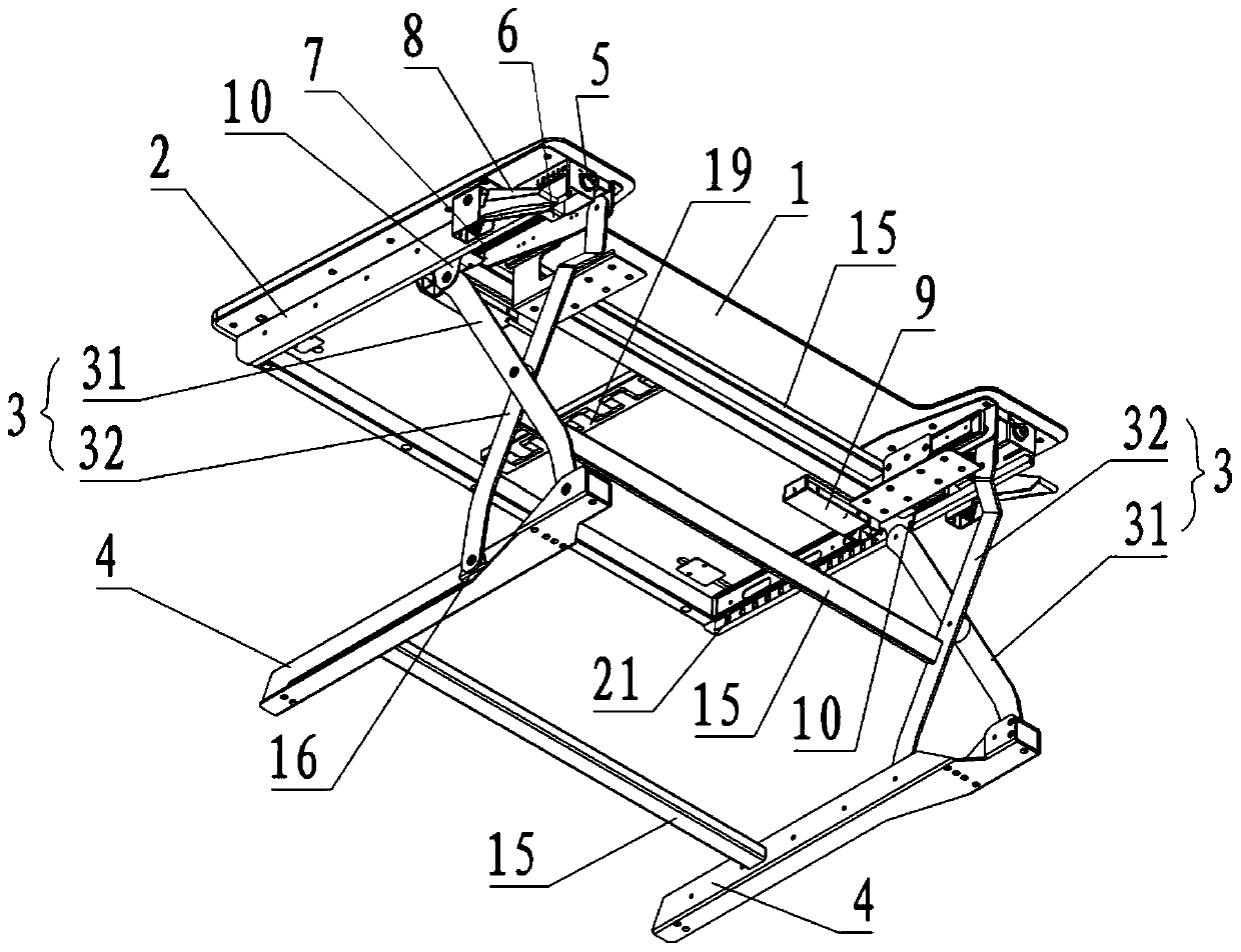
[0044] Such as figure 1 As shown, the lifting table provided by the embodiment of the present invention includes a desktop 1, a table frame 2, two X-shaped lifting frames 3, and two table legs 4, wherein the desktop 1 is arranged above the table frame 2, and the two X-shaped lifting frames Frames 3 are respectively provided on both sides of the table frame 2, and each table frame 2 is provided with a table leg 4 on the underside. Specifically, each X-shaped lifting frame 3 includes a first support portion 31 and a second support portion 32 , the middle part of the first supporting part 31 and the second supporting part 32 are hingedly fixed, the upper end of the first supporting part 31 is slidably connected with the table frame 2, and its lower end is hingedly fixed with the table leg 4, and the upper end of the second supporting part 32 is connected with the table frame 2 is hinged and fixed, and its lower end is slidably connected with the table legs 4, and the height of th...

Embodiment 2

[0069] Such as Figure 9 with Figure 10 As shown, the second embodiment is basically the same as the first embodiment, and the similarities will not be repeated. The difference is that an adjustment knob 20 for adjusting the torsion of the first torsion spring 12 is provided in the table leg 4, specifically, The adjustment knob 20 includes a dial 201, and above the dial 201, there are a plurality of support platforms 202 whose heights are successively increased, that is, a plurality of support platforms 202 are arranged in sequence from low to high along one direction, and the dial 201 partly exposes the table legs 4 In addition, it is convenient to adjust the torsion of the first torsion spring 12 through the dial 201. When the load on the table increases, the dial 201 is pulled so that the supporting platform 202 of the corresponding height is located on the lower side of the end of the first torsion spring 12, and the table can be lifted When descending, the first support...


PUM


Abstract

The invention relates to a lifting desk. The lifting desk comprises a desk frame, a desk top arranged above the desk frame and two X-shaped lifting frames arranged on two sides of the desk frame. Each X-shaped lifting frame comprises a first supporting portion and a second supporting portion, a tension spring is arranged between the upper end of the first supporting portion and the upper end of the second supporting portion, the movable end of the tension spring is connected with the first supporting portion, the fixed end of the tension spring is fixed to the desk frame through a distance adjusting device, the distance between the fixed end of the tension spring and the desk frame is adjusted by utilizing the distance adjusting device, and the pull force of the tension spring is matched with a load by changing the connecting pull force stroke length of the tension spring, so that the lifting process of the lifting desk is stable, effort is saved, and user experience is improved.

Description

technical field [0001] The invention relates to the technical field of office and study furniture, in particular to a lifting table. Background technique [0002] With the popularization and development of computer technology, more and more people work or study through computers. While computers bring convenience to people’s work and life, they also bring some negative impacts to people. People begin to use and sit in front of computers for a long time, resulting in frequent occurrence of occupational diseases such as cervical spondylosis and lumbar cone disease. More and more people put forward the concept of healthy office and study. [0003] Studies have shown that modern occupational diseases such as cervical spondylosis and lumbar cone disease can be better prevented if people use alternate sitting and standing postures to work , but these products generally have a complex structure and high cost, and existing enterprises need to eliminate the original desks and repla...

Claims


Application Information

Patent Timeline
Patent Type & Authority Patents(China)
IPC IPC(8): A47B9/16A47B9/00
CPCA47B9/00A47B9/16
Inventor 朱文彬
Owner 深圳米乔人因科技有限公司
Why Eureka
Try Eureka