Bag feeding and removing mechanism for beverage extraction device

A technology of extraction device and beverage pack, which is applied in the direction of beverage preparation device, application, household appliances, etc., can solve the problems of incomplete closing, splint opening and closing in place, unfavorable manufacturing, etc., and achieves a simple delivery process and a simple structure Effect

Active Publication Date: 2017-01-04
NINGBO QUANJING ELECTRIC TECH
View PDF11 Cites 7 Cited by
  • Summary
  • Abstract
  • Description
  • Claims
  • Application Information

AI Technical Summary

Problems solved by technology

[0005] 1. The left and right sides of the first component are used to guide and cooperate with the front outer surface of the groove. The guide surface has a first position and a second position, and the second position is located outside the first position and relatively forward. There is a smooth transition between the first position and the second position. The structure of the guide surface is complex and requires high machining accuracy, which is not conducive to manufacturing and increases manufacturing costs. Moreover, the opening and closing of the splint is realized through the cooperation of the guide surface and the hook, which is prone to jamming. In the dead case, the splint is not in place, so that the two parts cannot be completely closed during extraction.
[0006] 2. When packing, the splints on both sides are only limited by the side walls of the machine base to keep them moving inward. However, due to certain errors in assembly, the splints on both sides are loose, and the splints on both sides are loose. It will lead to the possibility that the blocking part at the front end of the splint will be stretched out, and then the blocking part at the front end of the splint will not

Method used


Image

  • Bag feeding and removing mechanism for beverage extraction device
  • Bag feeding and removing mechanism for beverage extraction device
  • Bag feeding and removing mechanism for beverage extraction device

Examples


Embodiment Construction

[0044] The present invention will be further described in detail below in conjunction with the accompanying drawings and embodiments.

[0045] Such as Figure 1-14 Shown is the first embodiment of the present invention.

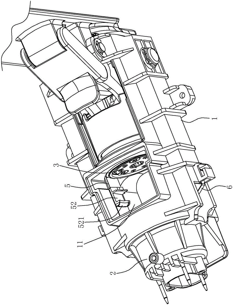
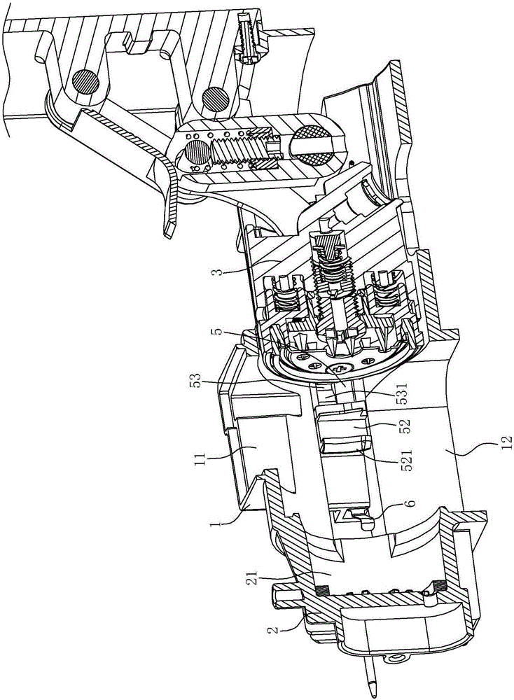
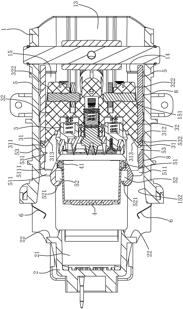
[0046] A delivery and unpacking mechanism for a beverage extraction device, comprising

[0047] A machine base 1 with a bag loading port 11 and a bag dropping port 12.

[0048] The first machine part 2 is fixed on the front part of the machine base 1 , and the first machine part 2 has an accommodating cavity 21 for accommodating a beverage bag 4 with a ring-shaped edge 41 .

[0049] The second machine part 3 is located at the rear of the base 1 and can slide forward and backward relative to the first machine part 2 driven by the driving structure. The driving structure can adopt a connecting rod structure, and reference can be made to the background patent, and of course a hydraulic driving structure can also be used. The machine base 1 and the first mach...


PUM


Abstract

The invention relates to a bag feeding and removing mechanism for a beverage extraction device. The mechanism comprises a machine base, a first part, a second part and two clamp plates, wherein a blocking portion is arranged at the front end of each clamp plate, and a groove is formed in front of each blocking portion. The mechanism is characterized in that blocking faces are arranged on the left side and right side of the first part, a guiding hole is formed in each clamp plate in the front-back direction, hook portions are arranged on the left side and right side of the second part, and the hook portions are located in the guiding holes and can slide front and back relative to the guiding holes; the front outer end face of each hook portion is in first contact fit with the front inner end face of the corresponding guiding hole, the rear hook face of each hook portion is in second contact fit with the rear inner end face of the corresponding guiding hole, a penetration hole allowing the corresponding hook portion to penetrate through is formed in each blocking portion, and the front inner end face of each hook portion is in third contact fit with the side face of the corresponding penetration hole. The mechanism is more reasonable in structural design, and bag removing and bag feeding are steadier and smoother.

Description

technical field [0001] The invention relates to a package-feeding and unpacking mechanism for a beverage extraction device with improved structure, wherein the beverage extraction device is mainly a coffee machine. Background technique [0002] Coffee machine is a kind of in beverage extracting device, and for making operation convenient, existing coffee machine has the function of realizing automatic unpacking. Such as the Chinese utility model patent "Automatic shedding mechanism of coffee bag in coffee machine" with the patent number ZL200720110811.2 (the announcement number is CN201044719Y), and the Chinese utility model patent "Beverage "Automatic Bag Dropping Mechanism of Preparation Device" both disclose a bag feeding and removing mechanism for a coffee machine. [0003] Both of the aforementioned two improved patents are equipped with two sets of guide grooves on the base to guide the front axle and the rear axle of the splint. There is no relative empty stroke bet...

Claims


Application Information

Patent Timeline
IPC IPC(8): A47J31/44
CPCA47J31/44
Inventor 景昱东徐平福
Owner NINGBO QUANJING ELECTRIC TECH
Why Eureka
Try Eureka