Adjustable interbody fixation and fusion device

An adjustable fusion cage technology, applied in the field of spinal intervertebral fusion surgery equipment, can solve the problem that the fusion cage cannot adapt well to changes in the height of the intervertebral space, it is not easy to fit into the intervertebral space, and the contact between the upper and lower vertebral bodies is not good, etc. problems, achieve good long-term effects, reduce medical expenses, and achieve good fusion effects

Inactive Publication Date: 2017-01-04
张衣北
View PDF5 Cites 7 Cited by
  • Summary
  • Abstract
  • Description
  • Claims
  • Application Information

AI Technical Summary

Problems solved by technology

However, fixed-height cages do not adapt well to changes in intervertebral space height
If the height is too high, it will not be easy to fit into the intervertebral space, and the implanted bone will be easily shaken out when hitting; if the height is too low, although it is easy to fit into the intervertebral space, it will not be in good contact with the upper and lower vertebral bodies, and bone fusion will not easily occur

Method used


Image

  • Adjustable interbody fixation and fusion device
  • Adjustable interbody fixation and fusion device
  • Adjustable interbody fixation and fusion device

Examples


Embodiment 1

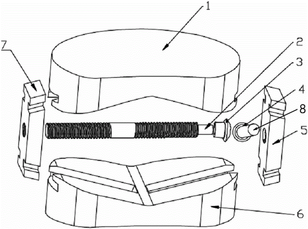
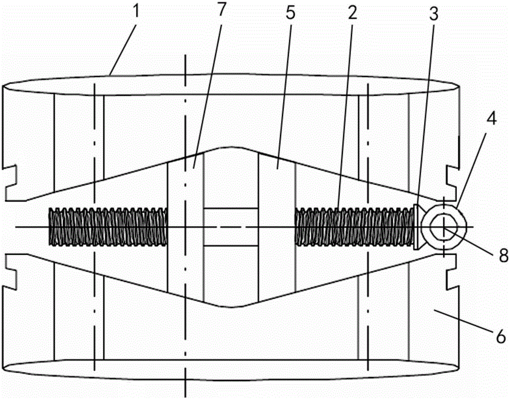
[0019] see figure 1 and 2 , the present embodiment is provided with upper support platform 1, lower support platform 6, left sliding support block 7, right sliding support block 5, rotating shaft 2, main rotating gear 4, from rotating gear 3 and handle 8; Said left sliding support Block 7 and right sliding support block 5 are respectively arranged on the left and right sides of upper supporting platform 1 and lower supporting platform 6, and described rotating shaft 2 is arranged between upper supporting platform 1 and lower supporting platform 6, and the left and right sides of rotating shaft 2 Ends are respectively connected with the left sliding support block 7 and the right sliding support block 5, the main rotating gear 4 is connected with the right end of the rotating shaft 2, the slave rotating gear 3 meshes with the main rotating gear 4, and the handle 8 is connected with the main rotating gear 4.

[0020] The upper support platform 1 is kidney-shaped, and the upper s...

Embodiment 2

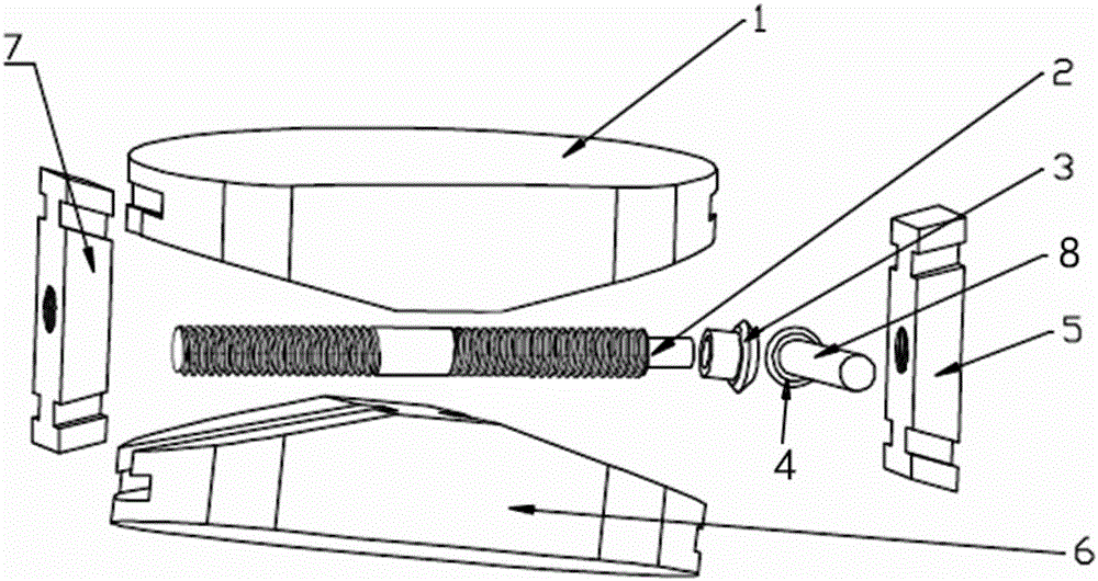
[0027] see image 3 and 4 , similar to Embodiment 1, the difference is that the opposite surfaces of the upper support platform 1 and the lower support platform 6 are slopes with low sides and high middle.


PUM


Abstract

The invention provides an adjustable interbody fixation and fusion device and relates to a spinal interbody fusion surgery instrument. The adjustable interbody fixation and fusion device is provided with an upper support platform, a lower support platform, a left sliding support block, a right sliding support block, a rotating shaft, a main rotating gear, an auxiliary rotating gear and a handle, wherein the left sliding support block and the right sliding support block are arranged on the left side and the right side of the upper support platform and the lower support platform respectively; the rotating shaft is arranged between the upper support platform and the lower support platform; the left end and the right end of the rotating shaft are connected with the left sliding support block and the right sliding support block respectively; the main rotating gear is connected with the right end of the rotating shaft; the auxiliary rotating gear is meshed with the main rotating gear; the handle is connected with the main rotating gear. With the adoption of the adjustable interbody fixation and fusion device, surgical operation can be simplified, surgical time can be shortened, the surgical treatment effect can be improved, and the medical expenses of a patient can be reduced; the height of the device can be adjusted according to the interbody space height, the fusion range of a kidney-shaped fusion surface is wider, the fusion effect of a bone trabecula structure is better, the surgical operation is more simplified, and the long-term effect of fixation and fusion is better.

Description

technical field [0001] The invention relates to a spinal intervertebral fusion surgical appliance, in particular to an adjustable intervertebral fixation fusion device. Background technique [0002] In spine surgery, Transforaminal lumbar interbody fusion (TLIF) technology is compared with Anterior lumbar interbody fusion (ALIF) and Posterior lumbar interbody fusion (Posterior lumbar interbody fusion). fusion, PLIF) technology is a newer spinal fusion technology. TLIF technology has the characteristics of less trauma, high fusion rate and compliance with spinal biomechanics, and it is gradually becoming dominant in the field of spinal fusion [Christopher P, Ames, Frank L, et al. Biomechanical comparison of posterior lumbar interbody fusion and transforaminal lumbar interbody fusion performed at 1 and 2 levels [J].Spine,2005,19:562-566; Annette Kettler,Werner Schmoelz,ErichKast.In vitro stabilizing effect of a transforaminal compared with two posterior lumbar interbody fusio...

Claims


Application Information

Patent Timeline
Patent Type & Authority Applications(China)
IPC IPC(8): A61F2/44
CPCA61F2/4465A61F2002/3006A61F2002/30133A61F2002/3036A61F2002/30772A61F2002/30863A61F2310/00023A61F2310/00796
Inventor 张衣北
Owner 张衣北
Why Eureka
Try Eureka