MAG welding fixture

A technology for welding tooling and spacers, applied in welding equipment, welding accessories, manufacturing tools, etc., can solve the problem of unsuitable welding tooling, and achieve the effect of ensuring the placement position

Inactive Publication Date: 2017-01-04
江苏凌云恒晋汽车零部件有限公司
View PDF1 Cites 0 Cited by
  • Summary
  • Abstract
  • Description
  • Claims
  • Application Information

AI Technical Summary

Problems solved by technology

But the above welding equipment is not suitable for MAG welding

Method used


Image

  • MAG welding fixture
  • MAG welding fixture
  • MAG welding fixture

Examples


Embodiment Construction

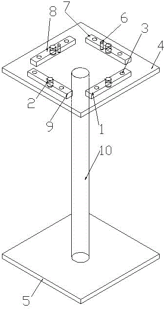
[0026] Such as figure 1 As shown in -7, a MAG welding tool includes a base 5, a support rod 10, a base 4, a first pad 1, a second pad 7, a third pad 8, and a fourth pad 9.

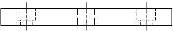
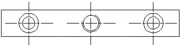
[0027] The base 4 is arranged above the base 5 via a support rod 10 . The base 4 is provided with the first spacer 1 , the second spacer 7 , the third spacer 8 and the fourth spacer 9 . The first cushion block 1, the second cushion block 7, the third cushion block 8, and the fourth cushion block 9 form a square. Positioning pins 2 are respectively provided on the first spacer 1 , the second spacer 7 , the third spacer 8 and the fourth spacer 9 .

[0028] Preferably, the first spacer 1 , the second spacer 7 , the third spacer 8 , and the fourth spacer 9 are connected to the base 4 through bolts.

[0029] Preferably, an anti-reversal pin 6 is provided on the second spacer 7 , and the anti-reverse pin 6 is arranged adjacent to the positioning pin 2 on the second spacer 7 .

[0030] Preferably, the first s...


PUM


Abstract

The invention discloses an MAG welding fixture, and belongs to the technical field of welding auxiliary equipment. The MAG welding fixture comprises a foundation, a supporting rod, a base, a first cushion block, a second cushion block, a third cushion block and a fourth cushion block. The base is arranged on the foundation through the supporting rod; the base is provided with the first cushion block, the second cushion block, the third cushion block and the fourth cushion block; the first cushion block, the second cushion block, the third cushion block and the fourth cushion block define a square; and the first cushion block, the second cushion block, the third cushion block and the fourth cushion block are each provided with a positioning pin. The MAG welding fixture is simple in structure, convenient to assemble, capable of effectively preventing deflection of parts and good in using performance.

Description

technical field [0001] The invention relates to a MAG welding tool and belongs to the technical field of welding auxiliary equipment. Background technique [0002] As shielding gas, Ar gas and CO are used 2 The MAG welding method of mixed gas of gas (5% by volume or more) or oxygen (1-10% by volume) is the most popular welding method, and it is widely used for welding steel materials because it is a high-efficiency welding method. In particular, due to the rapid spread of automatic welding, it has been widely used in shipbuilding, construction, bridges, automobiles, construction machinery and other fields. In the fields of shipbuilding, construction, and bridges, it is mostly used for high-current multilayer welding of thick beams and plates. On the other hand, in the fields of automobiles and construction machinery, it is mostly used for fillet welding of thin steel plates. . [0003] The Chinese invention patent with the publication number CN 103624421 A and the publica...

Claims


Application Information

Patent Timeline
Patent Type & Authority Applications(China)
IPC IPC(8): B23K9/173B23K9/32
CPCB23K9/173B23K9/32
Inventor 基军高立杨李明明周志冬金文海赵云胡岐山余刚
Owner 江苏凌云恒晋汽车零部件有限公司
Why Eureka
Try Eureka