A method and device for laser-induced double cavitation
A laser-induced and cavitation technology, applied in the laser field, can solve the problems of difficult to thoroughly study laser-induced cavitation technology, complex interaction between laser and liquid medium, etc., to achieve good processing effect, good thermal conductivity, and strong shock wave intensity. Effect
- Summary
- Abstract
- Description
- Claims
- Application Information
AI Technical Summary
Problems solved by technology
Method used
Image
Examples
Embodiment 1
[0049] The laser for processing is λ=1064nm, the pulse width is 10ns, and the laser repetition frequency is 1Hz.
[0050] Titanium alloy is selected as the material to be processed, and the liquid medium is water medium.
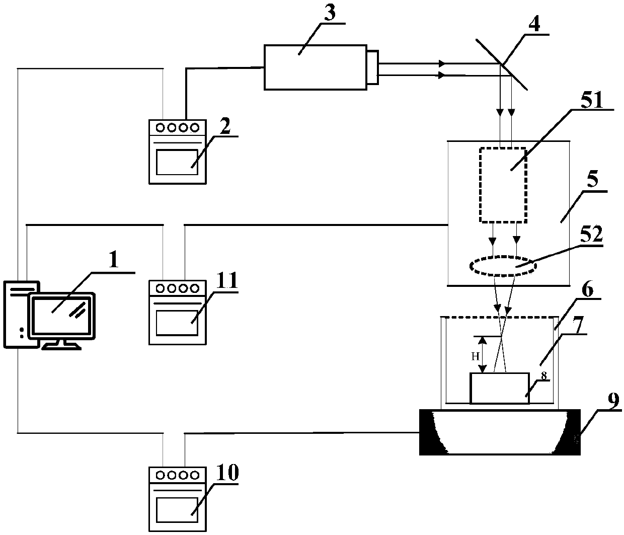
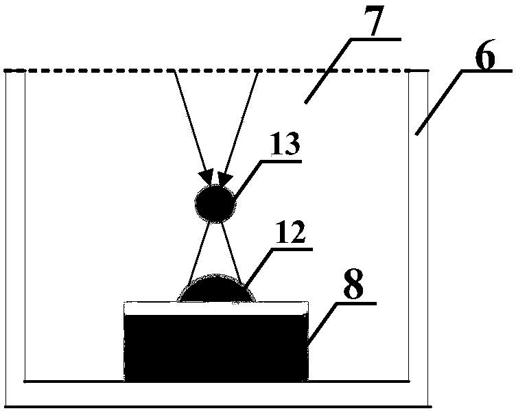
[0051] Place the glass container on the three-dimensional mobile platform and fix it. Place the material to be processed horizontally in a glass container and fix it. The H value is adjusted through the three-dimensional moving platform, and H=10mm is taken as the experimental experience value of double cavitation. Use a measuring cup to slowly inject the liquid medium into the glass container to avoid cavitation inside the liquid. The liquid level is at the top of the glass container, so that the water medium fills the entire glass container.
[0052] The beam expander focusing system was adjusted, and the breakdown threshold J of the water medium was measured experimentally 0 = 68mJ, the laser breakdown threshold of titanium alloy is 55mJ, according to ...
Embodiment 2
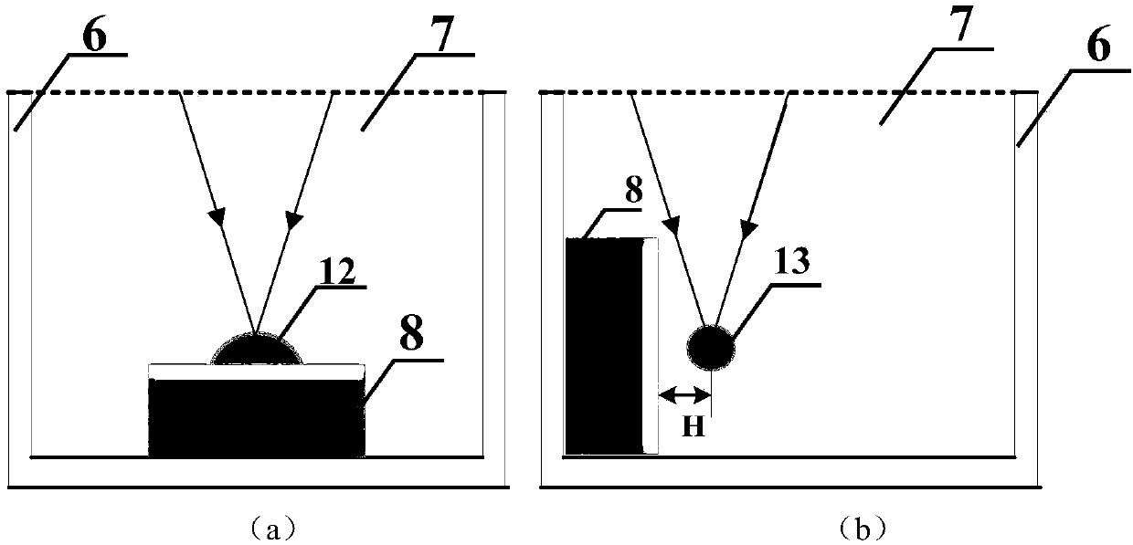
[0055] The laser energy value is 80mJ, which is slightly greater than the threshold value of laser breakdown in the water medium. Considering the loss of laser transmission in the device and the liquid medium, other parameter settings and devices are exactly the same as those in the embodiment, and the single cavitation pulsation sequence in the liquid medium is detected. Figure such as Figure 7 . At this time, the laser energy can only penetrate the liquid medium. When the laser beam is transmitted to the surface of the material to be processed, considering the absorption of the liquid medium 7 and the breakdown threshold of the surface of the material to be processed, no cavitation can be generated on the surface of the material to be processed. , forming single vacuoles.
Embodiment 3
[0057] Adjust the H value through the three-dimensional mobile platform, and take H=0mm. The laser energy is set to 60mJ, and other parameters are the same as in Example 1. The single cavitation pulsation sequence at the surface of the material to be processed is detected such as Figure 8 . At this time, the laser focus point is on the surface of the material to be processed, and the energy is large and exceeds the breakdown threshold of the surface of the material to be processed. The energy of other points is small and not enough to break down the liquid medium, so only cavitation is formed on the surface of the material to be processed. Because of the blocking effect of the surface of the material to be processed, the formed cavitation is semicircular rather than circular.
PUM
 Abstract
Description
Claims
Application Information
 - R&D
- Intellectual Property
- Life Sciences
- Materials
- Tech Scout
- Unparalleled Data Quality
- Higher Quality Content
- 60% Fewer Hallucinations
Browse by: Latest US Patents, China's latest patents, Technical Efficacy Thesaurus, Application Domain, Technology Topic, Popular Technical Reports.
© 2025 PatSnap. All rights reserved.Legal|Privacy policy|Modern Slavery Act Transparency Statement|Sitemap|About US| Contact US: help@patsnap.com


