Check patentability & draft patents in minutes with Patsnap Eureka AI!

Pressing mechanism for rotator commutation device

A commutator and rotor technology, used in metal processing, metal processing equipment, manufacturing tools, etc., can solve the problems of poor accuracy and damage of rotating cylinders, and achieve the effect of reducing force and improving service life.

Active Publication Date: 2017-01-04
浙江薪人机电科技有限公司
View PDF7 Cites 0 Cited by
  • Summary
  • Abstract
  • Description
  • Claims
  • Application Information

AI Technical Summary

Problems solved by technology

[0002] At present, the process of pressing the commutator onto the rotating shaft is generally to first grab the commutator with a grabbing rotary cylinder, and then use another extruding part to stamp the grabbing rod on the grabbing rotary cylinder, because the above-mentioned cylinder is Direct rigid impact on the grabbing rotary cylinder, so that the accuracy of the grabbing rotary cylinder will deteriorate or even be damaged after a period of use

Method used


Image

  • Pressing mechanism for rotator commutation device
  • Pressing mechanism for rotator commutation device
  • Pressing mechanism for rotator commutation device

Examples


Embodiment Construction

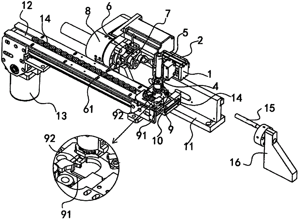
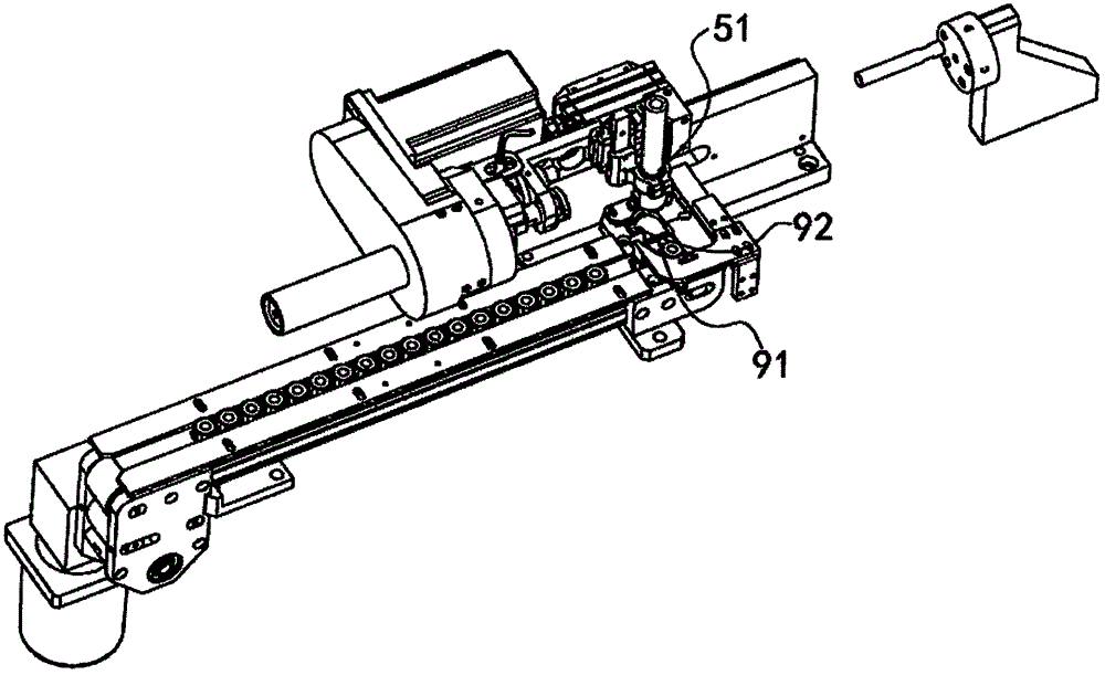
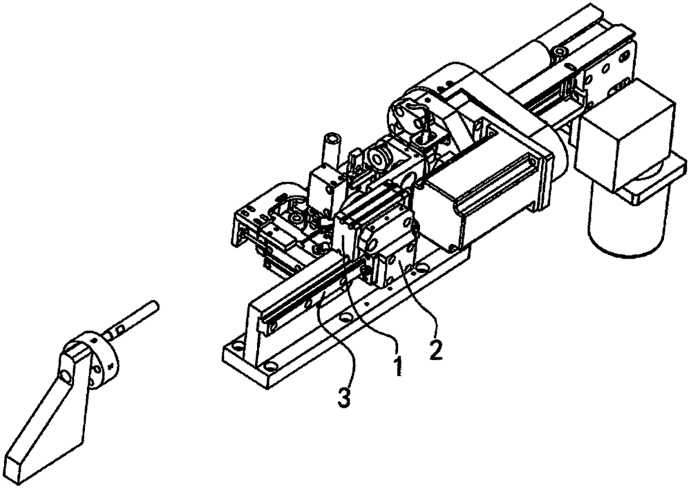
[0020] Please refer to Figure 1 to Figure 4 , the rotor commutator press-in mechanism in the figure includes a commutator grabbing rotary cylinder 1, a rotary cylinder slider 2, a guide rail 3, a pressing rod fixing part 4, a commutator pressing rod 5, a Spacer rod 6, a commutator pressure head 7, a commutator pressure head driver 8, a commutator block 9, a commutator into the block cylinder 10, a base plate 11, a commutator Transport track 12, a commutator transport drive mechanism 13.

[0021] The commutator grabs the rotary cylinder 1, which is a commonly used part at present, and it is a standard part, and a pressing rod fixing part 4 is installed at the position of the rotary head. The commutator grabs the rotary cylinder 1 and is fixed on the guide rail 3 through the rotary cylinder slider 2, and the above-mentioned guide rail 3 is fixed on the bottom plate 11, so that the commutator grabs the rotary cylinder 1 and can be on the above-mentioned slider 2 on the guide ra...


PUM


Abstract

The invention discloses a pressing mechanism for rotator commutation device, including a commutation device fetch rotation air cylinder, a rotation air cylinder slide block, a conducting track, a pressure rod fixed part, a commutation device pressure rod, a spacing rod, a commutation device pressure rod pressure head, a commutation device pressure head driver, a commutation device blocking piece, a commutation device feeding blocking piece air cylinder, a base floor, a commutation device conveying track, a commutation device conveying drive mechanism, a plunger; the commutation fetch rotation air cylinder is fastened on the conducting track through the rotation air cylinder slide block, the aforementioned conducting track is fastened on the base floor; the pressure rod is fastened on the commutation device fetch rotation air cylinder, the pressure rod fixed part cooperates with the commutation device pressure rod. The present invention can solve the technical problem of how to make the air cylinder to collide elastically with the fetch rotation air cylinder to increase its service life.

Description

technical field [0001] The invention relates to a rotor commutator pressing mechanism for pressing a commutator of a motor rotor onto a rotating shaft. Background technique [0002] At present, the process of pressing the commutator onto the rotating shaft is generally to first grab the commutator with a grabbing rotary cylinder, and then use another extruding part to stamp the grabbing rod on the grabbing rotary cylinder, because the above-mentioned cylinder is Direct rigid impact on the grabbing rotary cylinder, so that the accuracy of the grabbing rotary cylinder will deteriorate or even be damaged after a period of use. Contents of the invention [0003] The purpose of the present invention is to provide a rotor commutator press-in mechanism to solve the technical problem of how to make the cylinder that impacts the grabbing rotary cylinder elastically impact the grabbing rotary cylinder to improve the service life of the grabbing rotary cylinder. [0004] Rotor commu...

Claims


Application Information

Patent Timeline
IPC IPC(8): B23P19/027
CPCB23P19/027
Inventor 李水军朱武军秦进飞陆高丰魏成涛邵朝平
Owner 浙江薪人机电科技有限公司
Features
  • R&D
  • Intellectual Property
  • Life Sciences
  • Materials
  • Tech Scout
  • Unparalleled Data Quality
  • Higher Quality Content
  • 60% Fewer Hallucinations
Learn More