Positioning device used for connection rods and shell parts

A shell and parts technology, applied in the field of positioning devices, can solve the problems of difficult clamping and low positioning accuracy, and achieve the effects of high-precision positioning, solving low positioning accuracy, and easily clamping parts

Inactive Publication Date: 2017-01-04
WUXI RUIZHEN PRECISION MACHINERY
View PDF8 Cites 0 Cited by
  • Summary
  • Abstract
  • Description
  • Claims
  • Application Information

AI Technical Summary

Problems solved by technology

[0004] The purpose of the present invention is to provide a precise positioning device for connecting rods and shell parts to solve the problems of low positioning accuracy and difficult clamping in the prior art

Method used


Image

  • Positioning device used for connection rods and shell parts
  • Positioning device used for connection rods and shell parts
  • Positioning device used for connection rods and shell parts

Examples


Embodiment Construction

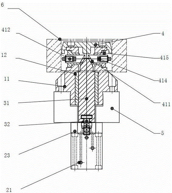
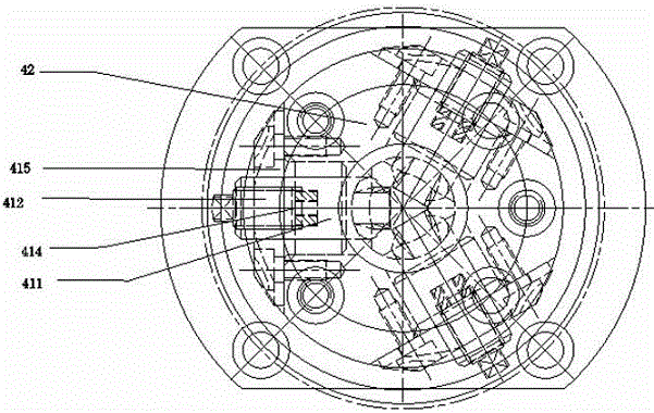
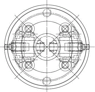
[0023] Combine below figure 1 , figure 2 , image 3 The connection mode and specific embodiments of the present invention will be described, and the present invention is not limited to the following connection mode and specific embodiments.

[0024] Combine below figure 1 The connection method of the present invention will be described.

[0025] A precise positioning device for connecting rods and shell parts, including a positioning sleeve device, a hydraulic device, a transmission device in the sleeve, and a guide pin device. One end of the transmission device in the sleeve is connected with the guide pin device, and the other end is connected with the guide pin device. The positioning sleeve device passes through and is connected to the hydraulic device.

[0026] The positioning sleeve device includes a positioning sleeve 11 and a pin sleeve 12. The positioning sleeve 11 is installed outside the pin sleeve 12, and the pin sleeve is located between the transmission device in the ...


PUM


Abstract

A positioning device used for connection rods and shell parts. The device comprises a positioning sleeve device, a hydraulic device, an in-sleeve transmission device and a guide pin device. One end of the in-sleeve transmission device is connected with the guide pin device, and the other end of the in-sleeve device penetrates through the positioning sleeve device and is connected with the hydraulic device. The in-sleeve transmission device comprises a pulling rod and a pulling nail, a T-type groove is formed in the end, close to the hydraulic device, on the pulling rod, the pulling nail is arranged in the T-type groove, and the pulling nail is connected with the hydraulic device. The other end of the pulling rod is evenly provided with dovetail inclined concave grooves. The guide pin device comprises a plurality of guide pin sets evenly distributed on the positioning plane. Each guide pin set comprises a guide pin and a positioning screw. A dovetail inclined convex groove is formed in one end of the inner side of each guide pin, and the shape, and the size and the position of each dovetail inclined convex groove correspond to those of the corresponding dovetail inclined concave groove. One end of the inner side of each guide pin extends to the axis of the in-sleeve transmission device. A flat bottom thread is arranged at one end of the outer side of each guide pin. The positioning screws are installed on the flat bottom threads. The positioning device has the advantages that a hydraulic expansion core positioning pin can achieve high-precision positioning, the parts can be easily clamped, and the problem that clamping for ensuring high-precision positioning is difficult is solved.

Description

Technical field [0001] The patent of the present invention relates to a positioning device, especially a precise positioning device for connecting rods and shell parts. Background technique [0002] Pin positioning is often used in connecting rods, reducer housings, transmission housings, clutch housings, intermediate housings and other technological equipment that are positioned by holes. Generally there are round pins and diamond pins, but ordinary round pins and diamond pins are Rely on tolerance to ensure positioning accuracy. When the tolerance is relatively small, the positioning accuracy is relatively high, but it will be difficult to clamp the parts at this time. When the tolerance is relatively large, the part clamping operation is easier, but the positioning accuracy will be reduced accordingly. Especially when the size of the positioning holes of some parts is relatively large, ordinary round pins and diamond pins are used for positioning, it will be difficult to cla...

Claims


Application Information

Patent Timeline
Patent Type & Authority Applications(China)
IPC IPC(8): B25B11/00
CPCB25B11/00
Inventor 许龙原兵波花耀君钱毅刚
Owner WUXI RUIZHEN PRECISION MACHINERY
Why Eureka
Try Eureka