Supercharge Your Innovation With Domain-Expert AI Agents!

Drilling device used for circuit board

A drilling device and circuit board technology, applied in metal processing and other directions, can solve the problems of low precision and slow drilling speed, and achieve the effects of improving precision, increasing drilling speed, and improving drilling accuracy

Inactive Publication Date: 2017-01-04
SICHUAN XINGZHI ZHIHUI INTPROP OPERATION CO LTD
View PDF7 Cites 1 Cited by
  • Summary
  • Abstract
  • Description
  • Claims
  • Application Information

AI Technical Summary

Problems solved by technology

Compared with many scientific research institutes or university laboratories, which use manual drilling, the precision is not high and the drilling speed is slow

Method used


Image

  • Drilling device used for circuit board

Examples


Embodiment 1

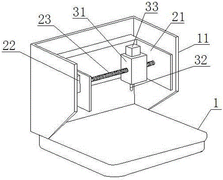
[0021] Such as figure 1 The shown drilling device for a circuit board includes a base 1, a drilling device and a support frame 11 arranged on the base 1, and is characterized in that it also includes a lateral control device and a longitudinal control device;

[0022] The lateral control device includes a bracket 21, a first driving device 22 fixed on the bracket 21 to control the rotation of the screw mandrel 23;

[0023] Described drilling device comprises the fixed block 31 that is threadedly connected with screw mandrel 23, drill bit 32 and is arranged on the fixed block 31 to drive the second driving device 33 that drill bit 32 rotates, and described fixed block 31 is close to the bottom of support 21;

[0024] The longitudinal control device includes a third drive device that pushes the bracket 21 to move in a direction perpendicular to the screw rod 23 , and the third drive device is fixed on the support frame 11 .

[0025] The fixed block 31 is close to the bottom of ...

Embodiment 2

[0027] Such as figure 1 A drilling device for circuit boards shown in the present embodiment is refined on the basis of the above embodiments, that is, the first driving device 22 is a motor.

[0028] The second driving device 33 is a motor.

[0029] The third driving device is a hydraulic cylinder.

Embodiment 3

[0031] Such as figure 1 A drilling device for a circuit board shown in this embodiment is refined on the basis of the above embodiment, that is, the first driving device 22 is fixed on the side wall of the bracket 21, Two opposite side walls of the bracket 21 are provided with screw fixing holes, and the screw rod 23 is penetrated in the screw fixing holes and threadedly connected with the screw fixing holes. The bracket 21 is "U"-shaped, so that the bracket has two opposite side walls, and the screw mandrel is fixed by using the two side walls, which can ensure the stability of the screw mandrel structure, and improve the drilling accuracy and drilling stability of the drilling device sex. The screw mandrel fixing hole is threadedly connected with the screw mandrel 23, and the tight connection between the threads can improve the fixing stability of the screw mandrel.


PUM


Abstract

The invention discloses a drilling device used for a circuit board. The device comprises a base, a drilling device body and a supporting frame on the base, and also comprises a transverse control device and a longitudinal control device. The transverse control device comprises a support and a first driving device fixed to the support so as to control a lead screw to rotate. The drilling device body comprises a fixing block connected with the lead screw through threads, a drill bit and a second driving device arranged on the fixing block to drive the drill bit to rotate, and the fixing block is attached to the bottom of the support. The longitudinal control device comprises a third driving device pushing the support to move in the direction perpendicular to the lead screw, and the third driving device is fixed to the supporting frame. The drilling device is high in drilling precision and drilling speed.

Description

technical field [0001] The invention relates to the field of circuit board processing devices, in particular to a drilling device for circuit boards. Background technique [0002] At present, professional circuit board manufacturers use large-scale CNC processing equipment to drill circuit boards. This large-scale drilling equipment is basically imported equipment, and the value is as high as hundreds of thousands. This large-scale equipment is not suitable for many universities, scientific research institutes and small enterprises. Compared with many scientific research institutes or university laboratories, which use manual drilling, the precision is not high and the drilling speed is slow. Contents of the invention [0003] In order to solve the above technical problems, the present invention provides a drilling device for circuit boards, which has high drilling precision and fast drilling speed. [0004] The technical solution adopted by the present invention to solv...

Claims


Application Information

Patent Timeline
Patent Type & Authority Applications(China)
IPC IPC(8): B26F1/16
CPCB26F1/16B26F2210/08
Inventor 贺昶明
Owner SICHUAN XINGZHI ZHIHUI INTPROP OPERATION CO LTD
Features
  • R&D
  • Intellectual Property
  • Life Sciences
  • Materials
  • Tech Scout
  • Unparalleled Data Quality
  • Higher Quality Content
  • 60% Fewer Hallucinations
Learn More