Driving mechanism of unmanned carrier

A technology for unmanned trucks and driving mechanisms, which is applied in the directions of motor vehicles, vehicle parts, transportation and packaging, etc., can solve the problems of insufficient driving force, high production cost, easy to go uphill, etc., and achieve sufficient driving force and production cost. low effect

Active Publication Date: 2017-01-04
太仓市梅林印刷感光材料有限公司
View PDF5 Cites 0 Cited by
  • Summary
  • Abstract
  • Description
  • Claims
  • Application Information

AI Technical Summary

Problems solved by technology

[0005] In order to overcome the disadvantages of the existing unmanned guided vehicles, such as high manufacturing cost and insufficient driving force, which make it difficult for unmanned guided vehicles to go uphill in rainy days, the technical problem to be solved by the invention is to provide a low-cost, Driving mechanism of unmanned guided vehicles with sufficient driving force to make it easy for unmanned guided vehicles to go uphill in rainy days

Method used


Image

  • Driving mechanism of unmanned carrier
  • Driving mechanism of unmanned carrier
  • Driving mechanism of unmanned carrier

Examples


Embodiment 1

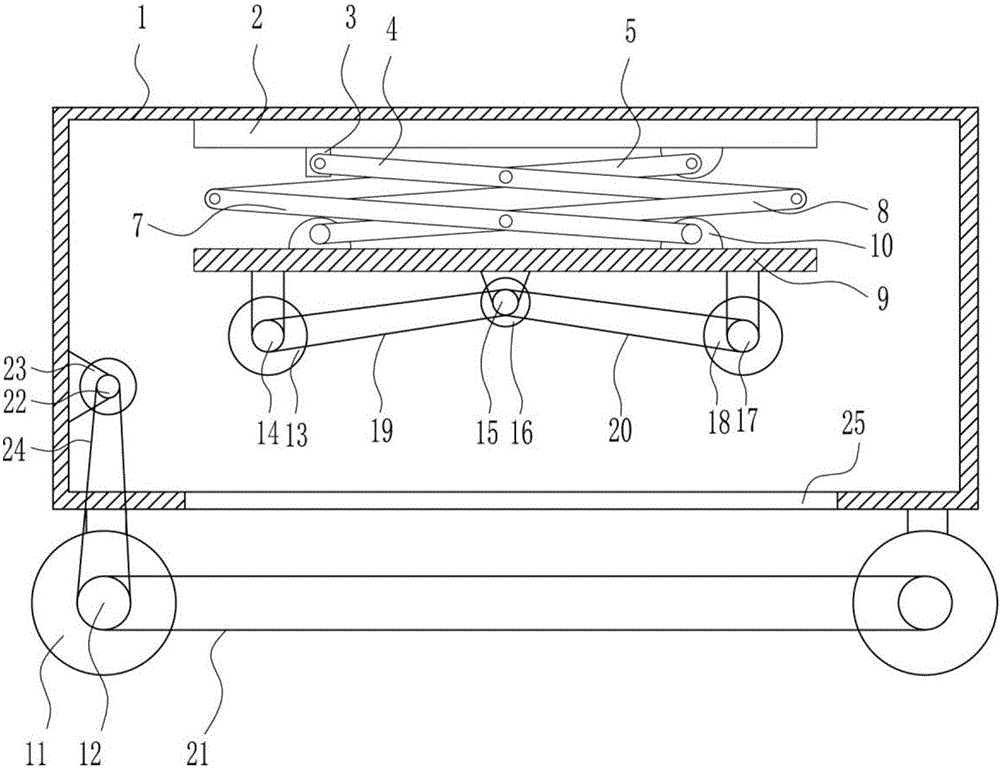
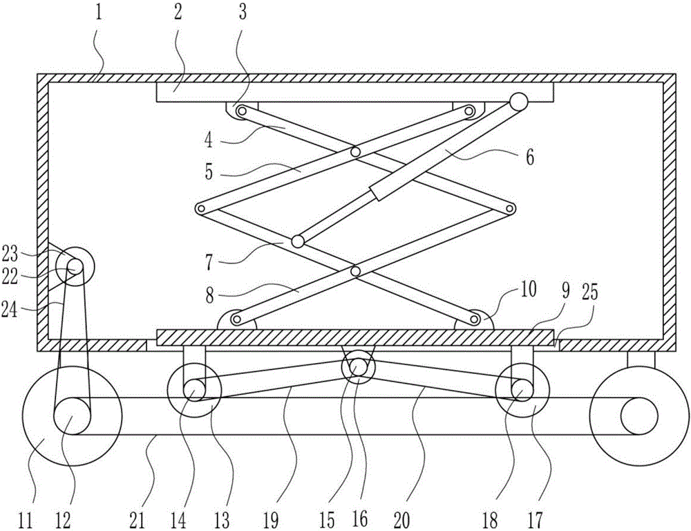
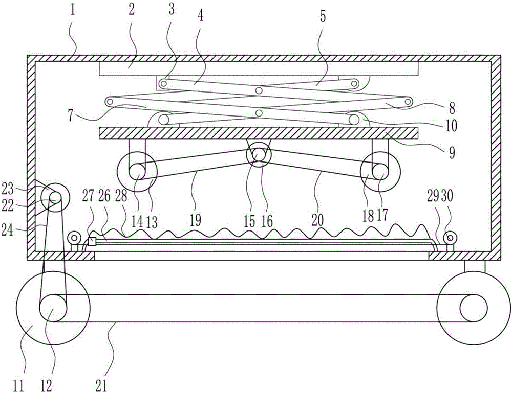
[0024] A driving mechanism for an unmanned guided vehicle, such as Figure 1-4 As shown, it includes a driving cavity 1, a top plate 2, a first swing seat 3, a first connecting rod 4, a second connecting rod 5, a cylinder 6, a third connecting rod 7, a fourth connecting rod 8, a fixed plate 9, The second swing seat 10, the first wheel 11, the first slave sprocket 12, the second wheel 13, the second slave sprocket 14, the first main sprocket 15, the second motor 16, the third wheel 17, the third slave Sprocket 18, the first chain belt 19, the second chain belt 20, the third chain belt 21, the second main chain wheel 22, the first motor 23 and the fourth chain belt 24, the top plate 2 is provided in the drive cavity 1 , the left and right sides of the bottom of the top plate 2 are provided with a first swing seat 3, the first swing seat 3 on the left side is hingedly connected with a first connecting rod 4, and the first swing seat 3 on the right side is hingedly connected with ...


PUM


Abstract

The invention belongs to the technical field of unmanned carrier manufacturing and particularly relates to a driving mechanism of an unmanned carrier to achieve the technical purposes of being low in manufacturing cost, sufficient in driving force and capable of making the unmanned carrier easily climb a slope on rainy days. To achieve the technical purposes, the driving mechanism of the unmanned carrier comprises a driving cavity , a top plate, a first swing base, a first connecting rod, a second connecting rod, an air cylinder, a third connecting rod, a fourth connecting rod, a fixing plate, a second swing base, first wheels, first driven chain wheels, a second wheel, a second driven chain wheel, a first main chain wheel, a second motor, a third wheel, a third driven chain wheel, a first chain belt, a second chain belt, a third chain belt, a second main chain wheel, a first motor and a fourth chain belt. The driving mechanism of the unmanned carrier achieves the advantages of being low in manufacturing cost, sufficient in driving force and capable of making the unmanned carrier easily climb a slope on rainy days.

Description

technical field [0001] The invention belongs to the technical field of unmanned transport vehicles, and in particular relates to a driving mechanism of an unmanned transport vehicle. Background technique [0002] Unmanned van refers to a transport vehicle equipped with automatic guidance devices such as electromagnetic or optical, capable of driving along a prescribed guiding path, with safety protection and various transfer functions, and a transport vehicle that does not require a driver in industrial applications. It uses a rechargeable battery as its power source. Generally, the computer can be used to control its travel route and behavior, or the electromagnetic track can be used to set up its travel route. The electromagnetic track is pasted on the floor, and the unmanned van will move and act according to the information brought by the electromagnetic track. [0003] When the unmanned guided vehicle goes uphill in rainy days, the driving force of the unmanned guided ...

Claims


Application Information

Patent Timeline
Patent Type & Authority Applications(China)
IPC IPC(8): B62D63/02B60K17/342
CPCB60K17/342B62D63/02
Inventor 李翔
Owner 太仓市梅林印刷感光材料有限公司
Why Eureka
Try Eureka