
Proving ring of load lifting limiter

A technology of lifting weight limiter and force measuring ring, which is applied in the direction of clockwork mechanism and hoisting device, can solve the problems of springback error, deformation coefficient, glue falling off and pressure block aging, etc., and achieves easy production and good structure Reasonable and easy to adjust the effect

Inactive Publication Date: 2017-01-04
扬州金鹤防水工程有限公司
View PDF0 Cites 0 Cited by
  • Summary
  • Abstract
  • Description
  • Claims
  • Application Information

AI Technical Summary

Problems solved by technology

[0003] The purpose of the present invention is to overcome the deficiencies of the deflection coefficient of the bow plate in the force measuring ring of the existing crane lifting protection device, the glue falling off, the aging of the pressure block, and the rebound error, and provide a lifting device with a small change in the ambient temperature and a limited lifting capacity. Force-measuring rings with good protection capacity limiter

Method used


Image

  • Proving ring of load lifting limiter

Examples


Embodiment Construction

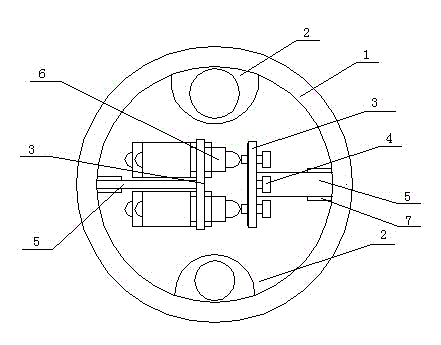
[0008] Two connecting sleeves 2 are welded on the inner side of the ring 1, and the fixing plate 7 is welded on the inner side of the other opposite side of the ring, and the connecting line of the two connecting sleeves is perpendicular to the connecting line of the two fixing plates. Install the connecting plate 5 and the mounting plate 3 on the two fixing plates 7 respectively through the connecting screws, respectively install four micro switches 6 and the adjusting screws 4 on the mounting plate 3, and pass the anti-loosening screws on the mounting plate where the adjusting screw 4 is installed. Install the anti-loosening plate, and the micro switch and the adjusting screw correspond to the same center line. A cover plate is arranged on the ring, and the shape of the force measuring ring is like a round cake. When installing and adjusting the force measuring ring, adjust the adjusting screws separately to achieve the purpose of alarming and power off, and then tighten the...


PUM


Abstract

The invention relates to a proving ring of a load lifting limiter, which belongs to the technical field of lifting safety protection. The proving ring comprises a circular ring, wherein two pairs of connecting sleeves and fixed plates which are perpendicular to each other are arranged in the circular ring, the connecting sleeves are arranged on the vertical plumb line of the inner side of the circular ring, the fixed plates are fixed to the horizontal line of the inner side of the circular ring, the connecting line of the centers of the two fixed plates is perpendicular to the connecting line of the centers of the two connecting sleeves, connecting plates are respectively arranged on the two fixed plates, microswitches are installed on one connecting plate on one side by virtue of mounting plates, adjusting screws are installed on the other connecting plate on the other side by virtue of mounting plates, and the microswitches correspond to the adjusting screws. The proving ring has the advantages of reasonable and simple structure, easiness in production and manufacturing, reasonable structure of a ring body and convenience in installation and adjustment, the microswitches, the adjusting screws, anti-loosing screws and anti-loosing plates are respectively installed on the fixed plates by virtue of the connecting plates, and the anti-loosing screws are arranged on the connecting plate between the two adjusting screws so as to extrude the anti-loosing plates, so that the adjusting screws are prevented from loosing, the limit to the lifting is facilitated, and overweight and accidents are avoided.

Description

technical field [0001] The invention relates to a protection device for controlling lifting overload, and belongs to the technical field of lifting safety protection. Background technique [0002] Cranes are widely used in all walks of life and are essential key equipment for large-scale project construction. The lifting capacity limiter is a safety protection measure for cranes. Lifting safety accidents occur frequently due to lifting overload, and installing a lifting weight limiter on the lifting machinery is an important guarantee to prevent such accidents from happening. The conventional lifting capacity limiter force-measuring ring includes a bow plate, a micro switch, an adjustment screw, and a control part of a lock nut. The control part uses glue to stick two bow plates in the force-measuring ring. One end of the force-measuring ring is fixed, and the other end is strung together with the pulley on the pin shaft and fixed with a loose washer. The pulley of the lift...

Claims


Application Information

Patent Timeline
Patent Type & Authority Applications(China)
IPC IPC(8): B66D1/56B66D1/58
Inventor 佘其根
Owner 扬州金鹤防水工程有限公司
Learn More