Eureka AIR delivers breakthrough ideas for toughest innovation challenges, trusted by R&D personnel around the world.

Construction method for joint section of continuous rigid frame aqueduct

A construction method and a technology of closing sections, which are applied in erecting/assembling bridges, bridge materials, bridges, etc., can solve problems such as the inability to use traditional closing methods for construction, high finishing force, continuous steel aqueduct passing water, etc., to facilitate load bearing The uniformity of distribution and the effect of solving the partial load of the cantilever beam

Active Publication Date: 2017-01-04
THE 2ND ENG OF THE 12TH BUREAU GROUP OF CHINA RAILWAY +1
View PDF9 Cites 13 Cited by
  • Summary
  • Abstract
  • Description
  • Claims
  • Application Information

AI Technical Summary

Problems solved by technology

[0004] In order to solve the problem that the traditional closing method cannot be used for construction due to the fact that the continuous steel structure aqueduct passes through the water and the finishing force is higher than that of road and railway bridges, the present invention further provides a construction method for the closing section of the continuous rigid structure aqueduct

Method used


Image

  • Construction method for joint section of continuous rigid frame aqueduct
  • Construction method for joint section of continuous rigid frame aqueduct
  • Construction method for joint section of continuous rigid frame aqueduct

Examples


Embodiment Construction

[0034] In conjunction with accompanying drawing, the specific embodiment of the present invention is described further:

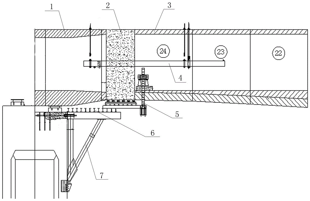
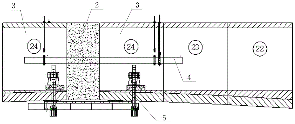
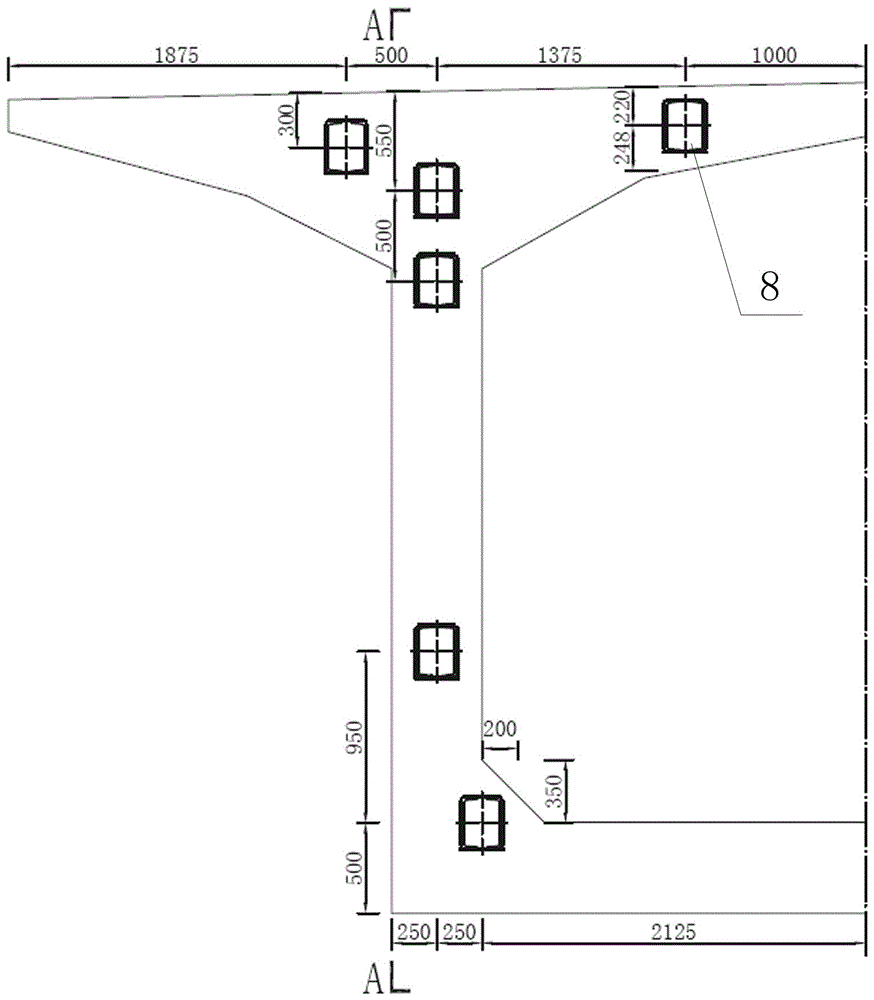
[0035] The main canal aqueduct C1 standard of the Qianzhong Water Conservancy Project Phase I project is the main channel of the grassland slope aqueduct with a continuous rigid structure of (95.95 + 180 + 95.95) m and a total length of 371.9 m. The main channel of the Xujiawan aqueduct is (95.95 + 2 × 180 + 95.95 )m continuous rigid structure, with a total length of 551.9m and a beam top width of 9.5m. Each main pier "T" structure is divided into 24 symmetrical beam sections in the longitudinal bridge direction. It is 12 meters (0# section), 8×3.0 meters, 10×3.5 meters, 6×4.0 meters, 2.0 meters (closed section), and the side-span cast-in-place section is 4.95 meters long.

[0036] There are 7 closing sections in the whole bidding section, which are 2 side span closing sections and 1 middle span closing section of Caodipo Aqueduct, 2 side span closing secti...


PUM

PropertyMeasurementUnit
Thicknessaaaaaaaaaa

Abstract

The invention belongs to the technical field of the construction of continuous rigid frame aqueducts, and particularly relates to a construction method for a joint section of a continuous rigid frame aqueduct. In order to solve the problems that because water flows through the continuous rigid frame aqueduct, integral force of the continuous rigid frame aqueduct is higher than that of a highway bridge or a railway bridge, so that the continuous rigid frame aqueduct cannot be constructed by a conventional joint method, the invention further provides the construction method of the joint section of the continuous rigid frame aqueduct. The construction method comprises the following steps of performing side span joint construction and a middle span joint construction, wherein side span joint construction is firstly performed, and then the middle span joint construction is performed; and before the joint construction, disassembling a hanging basket module and performing construction by a hoisting frame, wherein the joint construction process comprises the following steps of mounting the hanging basket, mounting a joint section module, performing strengthening framework construction, performing concrete construction, performing prestress construction and performing mud jacking. According to the construction method disclosed by the invention, a conventional hanging bracket construction method is changed, before the joint construction, the hanging bracket module is disassembled and the hoisting frame is mounted, so that the problem of offset loading of a cantilever beam caused by gravity of the hanging basket is solved, the operation of the joint construction is facilitated, and the bearing distribution uniformity of the joint section is improved.

Description

technical field [0001] The invention belongs to the technical field of construction of a continuous rigid-frame aqueduct, and in particular relates to a construction method for a closing section of a continuous rigid-frame aqueduct. Background technique [0002] Due to the shrinkage and creep of box girder concrete and changes in natural conditions (such as uneven sunlight, temperature difference between day and night, etc.), various deformations and internal forces will be generated within the closing section. When the concrete is hardened (concrete has not yet formed strength or the strength is very low), until the longitudinal continuous beam is stretched, the above-mentioned deformation will easily crack the concrete in the closed section due to the internal force caused by the change of the structural system in the box girder. Therefore, the closing of the box girder, that is, the system conversion, is a key process to control the stress and linearity of the full trough...

Claims


Application Information

Patent Timeline
IPC IPC(8): E01D21/00E01D101/28
CPCE01D21/00E01D2101/28
Inventor 杜强范廉明张玉民武明静李五红赵香萍黄亮李晓徐海龙沙金贵
Owner THE 2ND ENG OF THE 12TH BUREAU GROUP OF CHINA RAILWAY
Why Eureka
Eureka Blog
Learn More