Pipe body telescopic derrick (rotary pulley)

A telescopic, pole-holding technology, applied in building types, buildings, towers, etc., can solve problems such as difficulty in standing, difficult to reach height, and aggravating enterprise construction costs and operating risks.

Inactive Publication Date: 2017-01-04
YUECHI LICHENG ENVIRONMENT PROTECTION TECH
View PDF3 Cites 0 Cited by
  • Summary
  • Abstract
  • Description
  • Claims
  • Application Information

AI Technical Summary

Problems solved by technology

The standing and lifting of the pole requires a lot of waves (steel wires) to be mastered in the four corners. The current poles can only stand after multi-section assembly. Not only is it difficult to stand, but it is also difficult to reach the required height. , because it will be impossible to stand if it is extended a little longer, which will undoubtedly increase the construction cost of the enterprise and bring business risks

Method used


Image

  • Pipe body telescopic derrick (rotary pulley)
  • Pipe body telescopic derrick (rotary pulley)
  • Pipe body telescopic derrick (rotary pulley)

Examples


Embodiment Construction

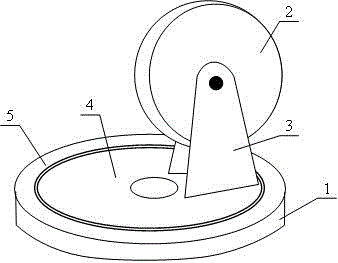
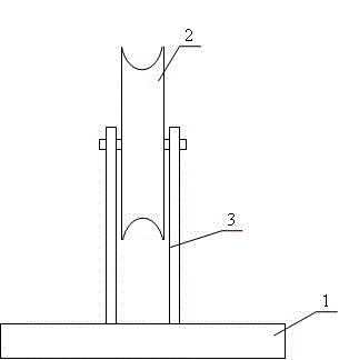
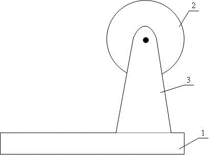
[0009] As shown in the figure, a telescopic tube holding pole (rotary pulley). The rotating pulley is installed on the top 1 of the holding pole. It can maintain the verticality of the steel wire rope of the top 1 of the holding pole. On one side of the bearing inner circle 4, the bearing outer circle 5 is closely matched with the top 1 of the holding rod, and the pulley groove and the center of the holding rod are on a straight line. According to which direction the hanger needs to hold the pole, the rotating pulley will automatically turn to that direction, which can keep the wire rope of the hanger always in the center of the hold pole. The defects of the prior art are solved, the construction is convenient, and the labor force and time are saved.


PUM


Abstract

The invention discloses a pipe body telescopic derrick (rotary pulley); the rotary pulley is arranged on a derrick top (1), and can keep the perpendicularity of a derrick top (1) hanger steel wire rope; a pulley (2) and a pulley seat (3) are arranged on one side of a bearing inner ring (4); a bearing outer ring (5) and the derrick top (1) are tightly matched and connected; centers of a pulley groove and the derrick are on a same straight line; if the hanger needs the derrick to shift to certain direction, the rotary pulley will automatically rotate to said direction.

Description

technical field [0001] The invention is applied to the construction of erecting iron towers for power transmission lines. Background technique [0002] The erection of transmission line towers all rely on poles to stand in the center of the tower as a support for lifting operations. The standing and lifting of the pole requires a lot of waves (steel wires) to be mastered in the four corners. The current poles can only stand after multi-section assembly. Not only is it difficult to stand, but it is also difficult to reach the required height. , because if it is longer, it will not be able to stand up, which will undoubtedly increase the construction cost of the enterprise and bring business risks. For this reason, it is urgent for people to research and invent suitable lifting equipment and put it into construction to avoid the above-mentioned difficult difficulties and improve construction production efficiency. This equipment solves many problems, but improving equipment t...

Claims


Application Information

Patent Timeline
Patent Type & Authority Applications(China)
IPC IPC(8): E04H12/34
Inventor 唐登巨
Owner YUECHI LICHENG ENVIRONMENT PROTECTION TECH
Why Eureka
Try Eureka