Centrifugal fan

A centrifugal fan and damper technology, used in mechanical equipment, machines/engines, liquid fuel engines, etc., can solve problems such as affecting production or use, increasing air supply resistance, and low air supply efficiency, and achieving smooth and reasonable air supply. The effect of large air volume and air supply

Active Publication Date: 2017-01-04
QINGDAO HAIER SPECIAL REFRIGERATION ELECTRIC APPLIANCE CO LTD +1
View PDF5 Cites 16 Cited by
  • Summary
  • Abstract
  • Description
  • Claims
  • Application Information

AI Technical Summary

Problems solved by technology

This will increase the cost, and in some special occasions, due to space constraints, multiple fans cannot be installed, which will affect production or use. In addition, the installation of external joints not only increases the cost but also greatly increases the air supply resistance, reducing the air volume. , low air supply efficiency

Method used


Image

  • Centrifugal fan
  • Centrifugal fan
  • Centrifugal fan

Examples


Embodiment Construction

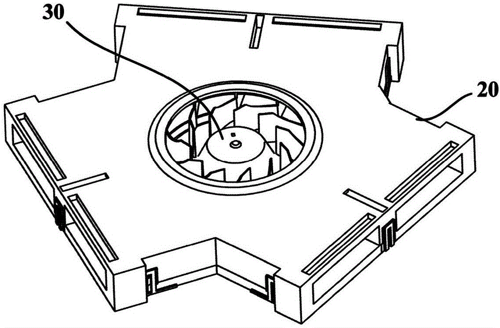
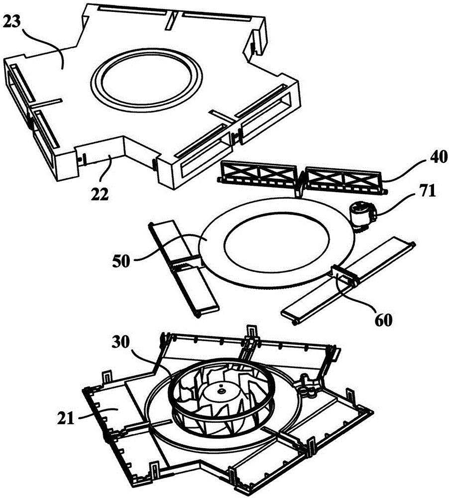
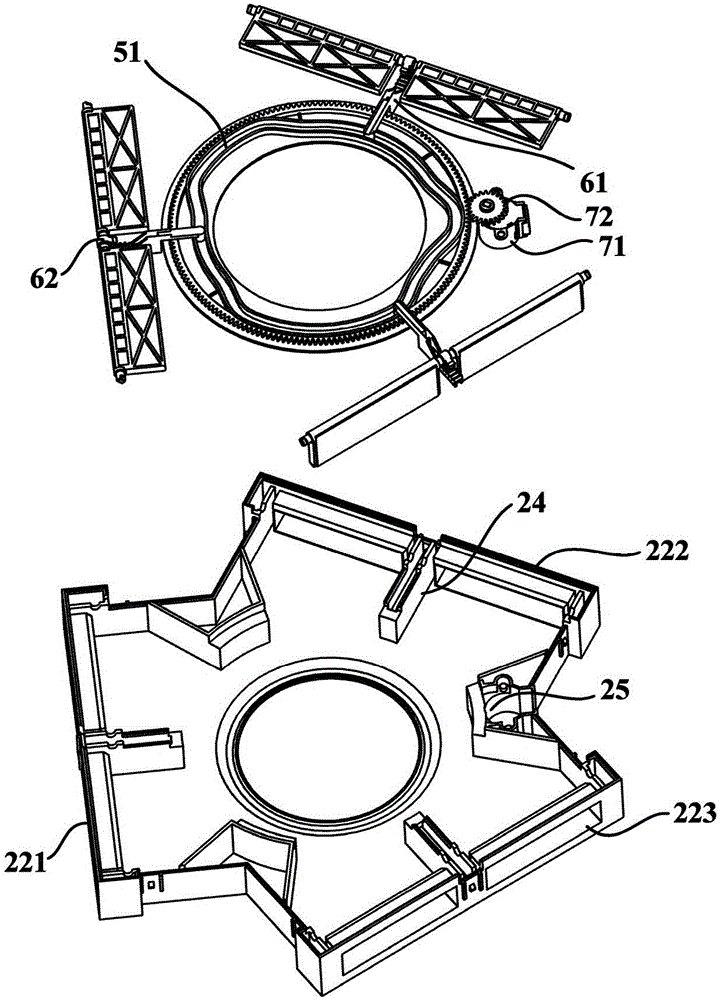
[0040] figure 1 is a schematic structural diagram of a centrifugal fan according to an embodiment of the present invention; figure 2 and image 3 They are respectively a schematic exploded view of a centrifugal fan and a schematic exploded view of a partial structure according to an embodiment of the present invention. Such as Figure 1 to Figure 3 As shown, the embodiment of the present invention provides a centrifugal fan. The centrifugal fan may include a casing 20 , a wind wheel 30 , multiple sets of damper flaps 40 , a rotating member 50 and a transmission mechanism 60 .

[0041] The case 20 may have a bottom case part 21 , a peripheral wall part 22 and a cover part 23 . Specifically, the bottom case part 21 may be in the shape of a plate, and the cover part 23 may also be in the shape of a plate. The peripheral wall portion 22 can be integrally formed with the cover portion 23 , that is, the peripheral wall portion 22 extends from the cover portion 23 to the bottom...


PUM


Abstract

The invention provides a centrifugal fan. The centrifugal fan comprises a shell, a wind wheel, a plurality of groups air door catches, a rotating piece and a transmission mechanism, wherein an air inlet is formed in the cover plate of the shell, and a plurality of groups of air outlets are formed in the peripheral wall part of the shell; the wind wheel is arranged as that air flow is forced to flow in the shell from the air inlet and flow out of the shell through one or more of the plurality of air outlets; each air door catch is arranged at the air outlet movably and arranged that a controlled place is moved to different shading positions so as to completely shade, partially shade or completely expose the air outlet, so that the air outlet area of the air outlet can be adjusted; the rotating piece is rotatably arranged on the shell; and the transmission mechanism is arranged as that the rotation motion of the rotating piece is transmitted to the plurality of air door catches. According to the centrifugal fan, the air door catches can be driven to move through the rotation of the rotating piece, so as to controllably shade the plurality of air outlet and realize the air supply for a plurality of directions, the air outlet directions can be selected, and the air outlet volume of each air outlet can be adjusted to realize reasonable air supply.

Description

technical field [0001] The invention relates to the technical field of fan air supply, in particular to a centrifugal fan. Background technique [0002] Existing centrifugal fans are provided with only one air outlet. When it is necessary to supply air to two or more different directions or multiple positions, it is necessary to install multiple fans or add external joints matching the fans to meet the needs of different directions or locations. The demand for air supply in multiple locations. This will increase the cost, and in some special occasions, due to space constraints, multiple fans cannot be installed, which will affect production or use. In addition, the installation of external joints not only increases the cost but also greatly increases the air supply resistance, reducing the air volume. , The air supply efficiency is low. Contents of the invention [0003] An object of the present invention is to overcome at least one defect of the existing centrifugal fan...

Claims


Application Information

Patent Timeline
IPC IPC(8): F04D17/08F04D29/42F04D29/46F04D27/00
CPCF04D17/08F04D27/002F04D29/4246F04D29/464
Inventor 费斌程学丽纪璇李登强
Owner QINGDAO HAIER SPECIAL REFRIGERATION ELECTRIC APPLIANCE CO LTD
Why Eureka
Try Eureka