
Low-noise window air conditioner

A window-type air conditioner and low-noise technology, applied in the field of low-noise window-type air conditioners, can solve problems such as being unsuitable for quiet places and use, and achieve the effect of smooth air outlet and noise reduction

Inactive Publication Date: 2017-01-04
赵原晓
View PDF3 Cites 11 Cited by
  • Summary
  • Abstract
  • Description
  • Claims
  • Application Information

AI Technical Summary

Problems solved by technology

However, the noise generated by the existing window air conditioners on the indoor side is generally above 50 decibels, which is not suitable for use in places that require quietness

Method used


Image

  • Low-noise window air conditioner
  • Low-noise window air conditioner
  • Low-noise window air conditioner

Examples


Embodiment 1

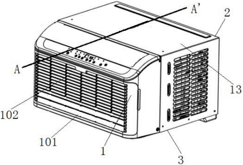
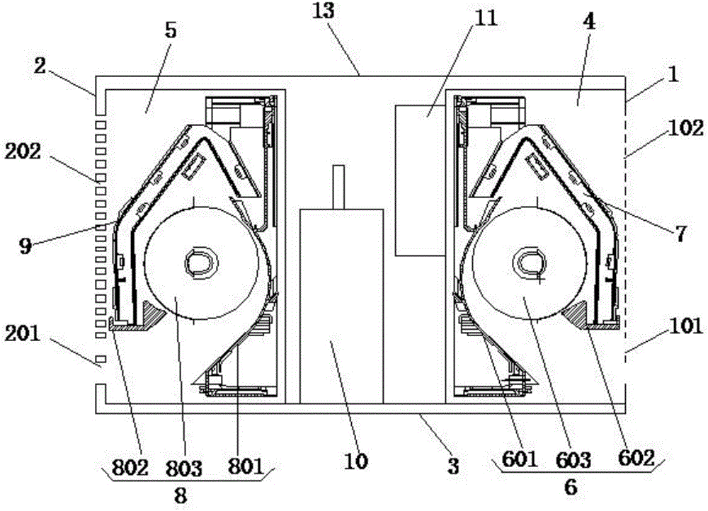
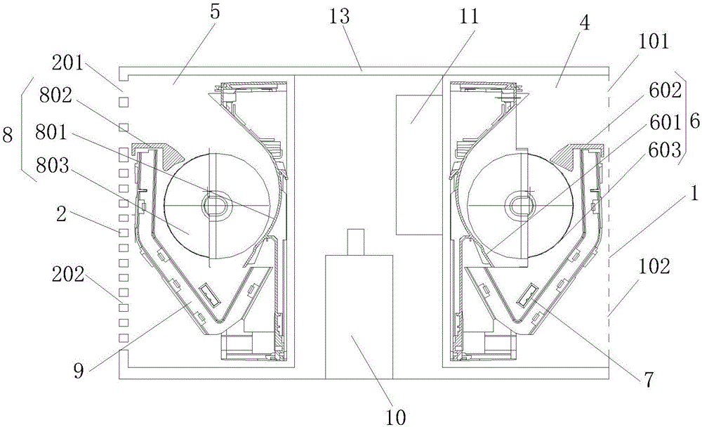
[0022] Such as figure 1 with 2 As shown, Embodiment 1 of the present invention relates to a low-noise window-type air conditioner, comprising: a housing surrounded by an indoor panel 1, an outdoor panel 2, a chassis 3 and a shell 12, and the inside of the housing includes a first The space area 4 and the second space area 5 close to the outdoor panel 2; the first space area 4 is provided with a first cross-flow fan 6 with the exhaust direction facing the indoor panel 1 and an indoor fan partly surrounding the first cross-flow fan 6 The heater 7; the indoor panel 1 is provided with an indoor air outlet 101 and an indoor air inlet 102; the second space area 5 is provided with a second cross-flow fan 8 with the exhaust direction facing the outdoor panel 2 and a second cross-flow fan 8 partially surrounding the second cross-flow fan. The outdoor side heat exchanger 9 of the fan 8; the outdoor panel 2 is provided with an outdoor air outlet 201 and an outdoor air inlet 202; the hou...

Embodiment 2

[0040] The difference between this embodiment and Embodiment 1 is that the indoor heat exchanger 7 is a three-stage type, which includes a vertical section above the first cross-flow fan 6 and a two-stage oblique section below the first cross-flow fan 6. Directional heat exchanger, compared with the plate evaporator, can effectively increase the air intake area, the height reaches 90% of the height of the window air conditioner, and the area reaches 100% of the frontal area of ​​the window air conditioner, not only can increase the heat exchange area, but also can The air intake is smoother, and the window air conditioner has a compact structure and a smaller volume.

[0041] The upper end of the indoor side heat exchanger 7 is located in front of the first volute tongue 602 , and the lower end thereof is in contact with the lower end of the first volute case 601 . The first volute tongue 602 is arranged on the upper end of the first cross-flow vane 603 , and the indoor air in...


PUM


Abstract

The invention relates to a low-noise window air conditioner. The low-noise window air conditioner comprises a shell defined by an indoor panel, an outdoor panel, a chassis and a housing, wherein the shell has a first space region near the indoor panel and a second space region near the outdoor panel inside; a first cross-flow fan of which the exhaust direction faces the indoor panel and an indoor heat exchanger which partially surrounds the first cross-flow fan are arranged inside the first space region; an indoor air outlet and an indoor air inlet are correspondingly formed in the indoor panel; a second cross-flow fan of which the exhaust direction faces the outdoor panel and an outdoor heat exchanger which partially surrounds the second cross-flow fan are arranged inside the second space region; and an outdoor air outlet and an outdoor air inlet are correspondingly formed in the outdoor panel. According to the low-noise window air conditioner, both an indoor fan and an outdoor fan adopt the cross-flow fans, compared with traditional axial flow fans and centrifugal fans, the cross-flow fans enable air inlet and air outlet of the window air conditioner to be smoother, and the noise generated by the window air conditioner is remarkably reduced.

Description

technical field [0001] The invention relates to an air conditioner adjustment technology, in particular to a low-noise window type air conditioner. Background technique [0002] The window air conditioner is usually installed on the wall. One part of the window air conditioner is located outdoors, and the other part is located indoors. Indoor heat exchanger and other structures, compared to the split unit, the window air conditioner is an integrated device of the refrigeration system on the indoor side and the outdoor side. However, the noise generated by the existing window-type air-conditioning products on the indoor side is generally above 50 decibels, which is not suitable for use in places that require quietness. Contents of the invention [0003] The invention provides a low-noise window-type air conditioner to solve the above technical problems. [0004] In order to achieve the above object, the technical solution of the present invention is achieved as follows: a...

Claims


Application Information

Patent Timeline
IPC IPC(8): F24F1/02F24F13/24F24F13/30
CPCF24F1/027F24F13/24F24F13/30F24F2013/247
Inventor 赵原晓
Owner 赵原晓
Learn More