
Desktop dust collector

A technology for vacuum cleaners and dust cups, which is applied in the installation of vacuum cleaners, suction filters, electrical equipment, etc., can solve the problems of limited performance of desktop vacuum cleaners, low utilization of space in the shell, and bloated overall structure of the product. The effect of good heat dissipation and less contact area

Pending Publication Date: 2020-09-25
BEAR ELECTRICAL APPLIANCE CO LTD +1
View PDF0 Cites 1 Cited by
  • Summary
  • Abstract
  • Description
  • Claims
  • Application Information

AI Technical Summary

Problems solved by technology

At present, most of the desktop vacuum cleaners on the market center the vacuum cleaner motor and the air inlet of the dust cup. Although this design is simple in structure, the central arrangement of the vacuum cleaner motor makes the width of the vacuum cleaner’s inner space equal, and lacks a large width space for installation. For large components, the diameter of the shell can only be increased to accommodate the installation of large components, resulting in a low utilization rate of space inside the shell and a bloated overall structure of the product
[0003] For example, in the technical solution disclosed in Chinese patent 201720987916X, due to the distribution and volume of the product components, only a small vacuum cleaner motor can be installed in the casing, and the suction force of the small vacuum cleaner motor is small, which limits the performance of the desktop vacuum cleaner and poor dust collection ability.

Method used


Image

  • Desktop dust collector
  • Desktop dust collector
  • Desktop dust collector

Examples


Embodiment Construction

[0028] The present invention will be described in further detail below in conjunction with the accompanying drawings.

[0029] This specific embodiment is only an explanation of the present invention, and it is not a limitation of the present invention. Those skilled in the art can make modifications to this embodiment without creative contribution as required after reading this specification, but as long as they are within the rights of the present invention All claims are protected by patent law.

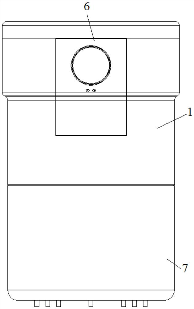
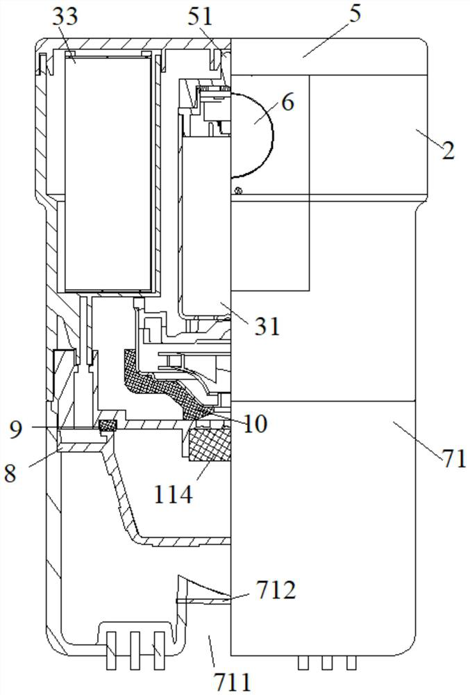
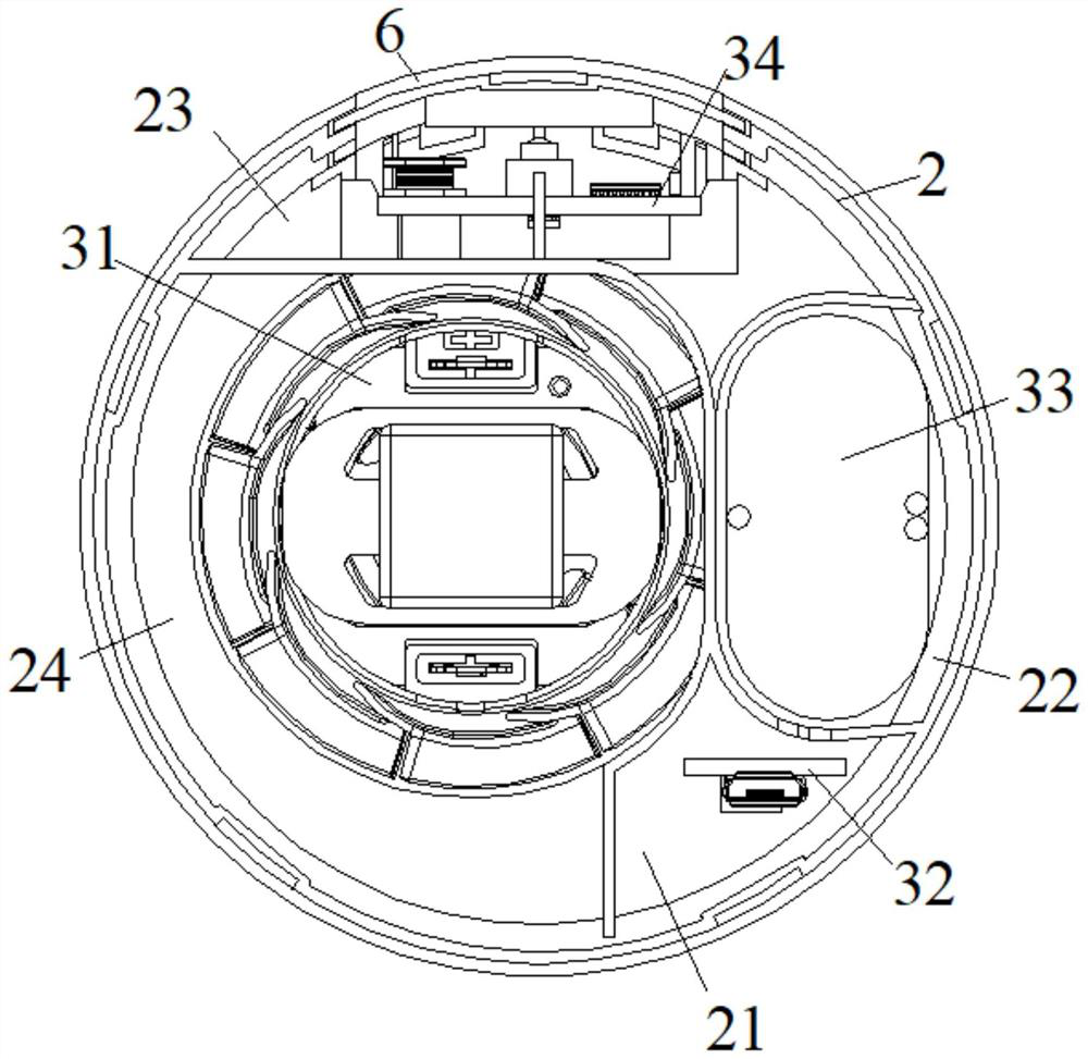
[0030] see Figure 1 to Figure 4 As shown, a desktop vacuum cleaner includes a casing 2 and a vacuum cleaner main body 1 disposed in the casing 2. The vacuum cleaner main body 1 includes a vacuum cleaner motor 31, a dust collection assembly 7, and an auxiliary device electrically connected to the vacuum cleaner motor 31. The vacuum cleaner motor 31 has an air suction port and an air exhaust port, the air suction port is connected to the dust collecting assembly 7; the vacuum clea...


PUM


Abstract

The invention relates to a desktop dust collector, which comprises a shell and a dust collector main machine arranged in the shell, the dust collector main machine comprises a dust collector motor, adust collection assembly and an auxiliary device electrically connected with the dust collector motor, the dust collector motor is provided with an air suction opening and an air exhaust opening, andthe air suction opening is connected with the dust collection assembly; the dust collector motor is vertically arranged in the shell, and the exhaust inlet is located below the exhaust outlet; the central axis of the dust collector motor does not coincide with the central axis of the shell so that the dust collector motor can be eccentrically arranged in the shell. According to the dust collector,the dust collector motor is eccentrically arranged in the shell, the structure is optimized, the space utilization rate is increased, the heat dissipation performance of the dust collector motor is improved, space is provided for the design of an air duct which is smooth up and down and free of bending, and therefore the dust collector has a good dust collection effect.

Description

technical field [0001] The invention relates to the field of household appliances, in particular to a desktop vacuum cleaner. Background technique [0002] Vacuum cleaner is a device that uses negative pressure to suck up dust and other dirt and collect them together. With the rapid development of technology and the continuous change of user needs, vacuum cleaners have also evolved into different types, such as horizontal vacuum cleaners, upright vacuum cleaners and handheld vacuum cleaners. vacuum cleaner etc. At present, most of the desktop vacuum cleaners on the market place the vacuum cleaner motor and the air inlet of the dust cup in the center. For large parts, the diameter of the shell can only be increased to accommodate the installation of large parts, resulting in a low utilization rate of the space inside the shell and a bloated overall structure of the product. [0003] For example, in the technical solution disclosed in Chinese patent 201720987916X, due to the...

Claims


Application Information

Patent Timeline
IPC IPC(8): A47L9/10A47L9/12A47L9/28A47L9/00
CPCA47L9/10A47L9/12A47L9/2868A47L9/2884A47L9/00
Inventor 李一峰李浩余水勇
Owner BEAR ELECTRICAL APPLIANCE CO LTD
Learn More