
LED test device and test method

A test device and a technology to be tested are applied in the direction of measuring devices, single semiconductor device testing, and electrical measurement, which can solve problems such as LED light intensity errors and achieve accurate light intensity and high reliability.

Active Publication Date: 2017-01-04
RESEARCH INSTITUTE OF TSINGHUA UNIVERSITY IN SHENZHEN
View PDF8 Cites 9 Cited by
  • Summary
  • Abstract
  • Description
  • Claims
  • Application Information

AI Technical Summary

Problems solved by technology

[0005] However, in the actual measurement process, there may be errors in the LED light intensity measured by the above three test methods

Method used


Image

  • LED test device and test method
  • LED test device and test method
  • LED test device and test method

Examples


Embodiment Construction

[0032] The preferred embodiments of the invention will be further described in detail below.

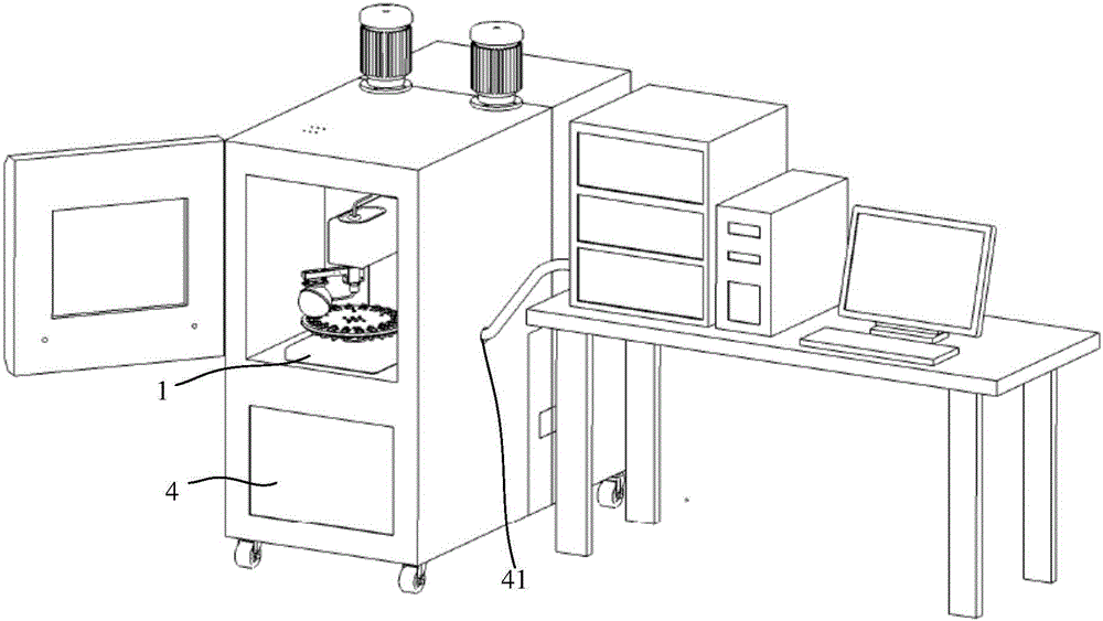
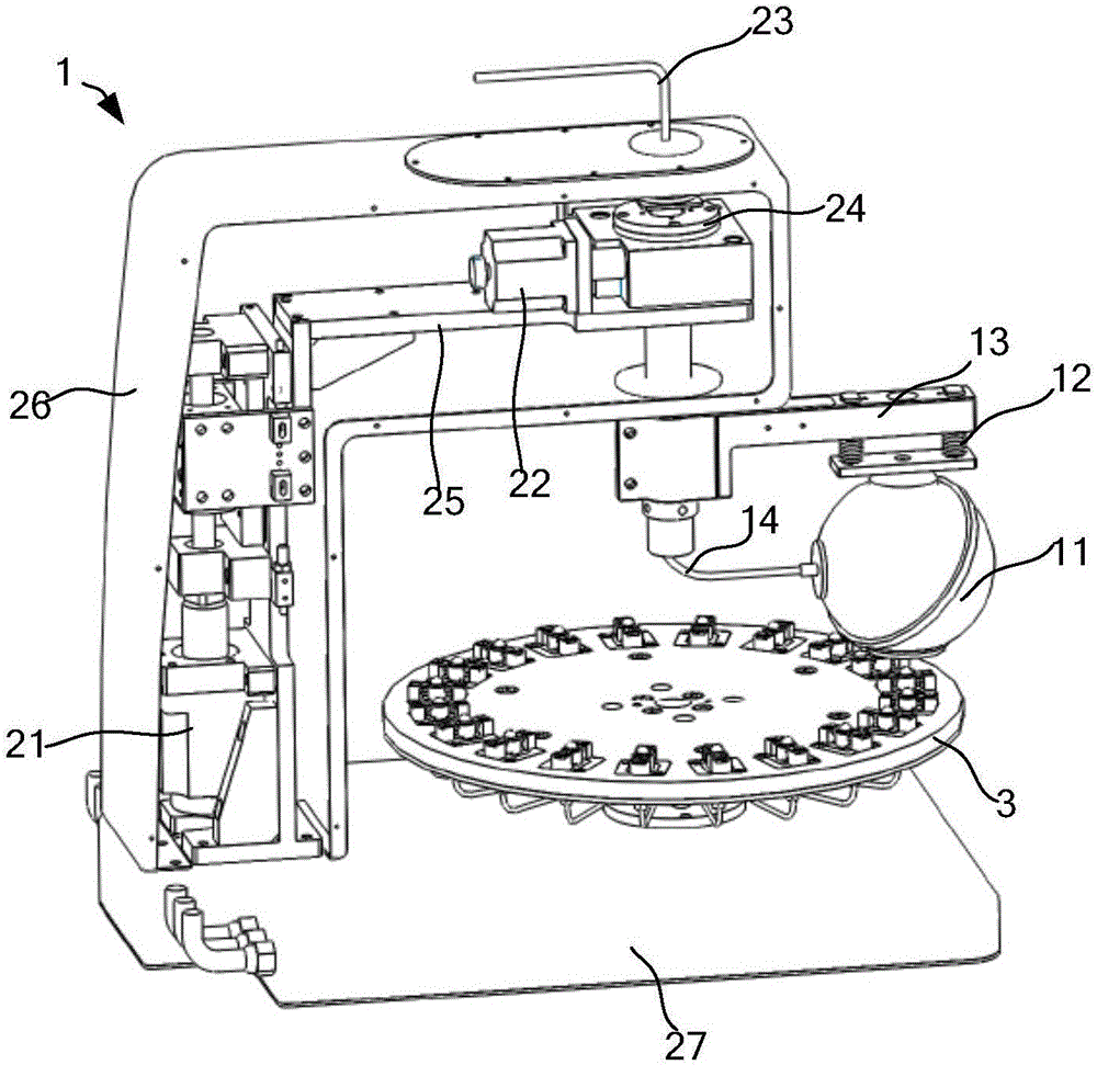
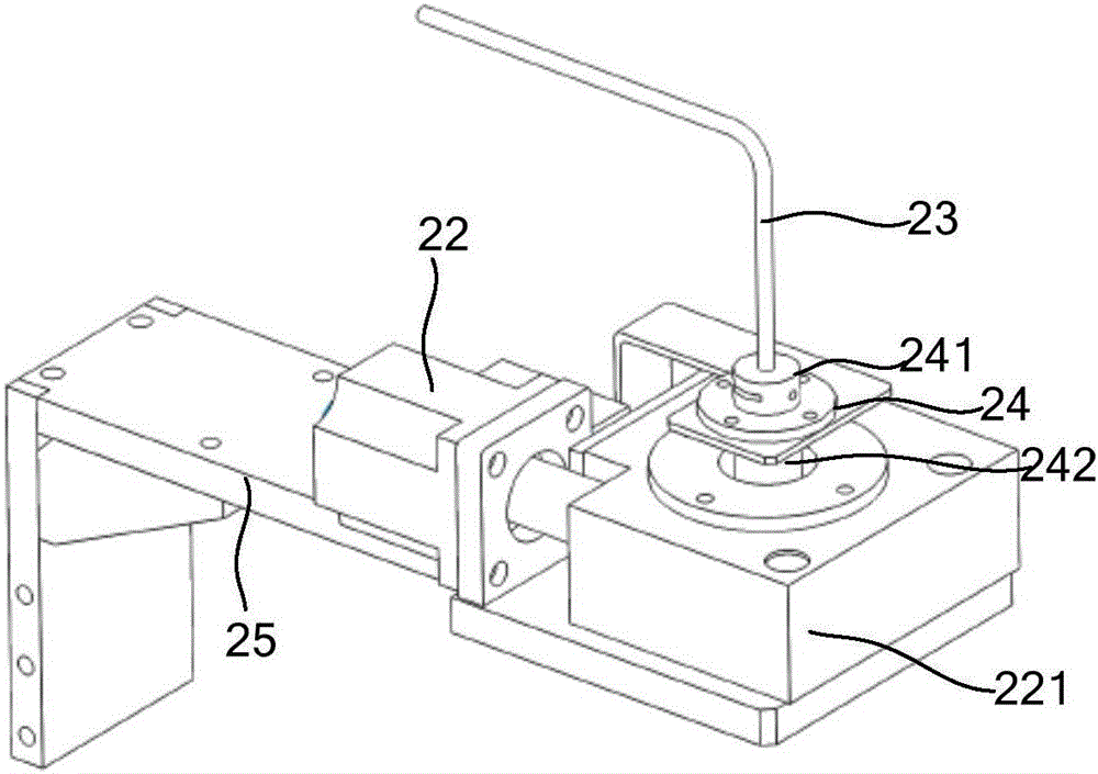
[0033] Such as Figures 1 to 6 As shown, the LED test device 1 of an embodiment includes a lifting drive device 21, a rotary drive device 22, an integrating sphere 11 and an integrating sphere tilt angle adjustment component 12, and the rotary driving device 22 is used to drive the integrating sphere 11 Rotate to align the tested LED 31 , the lifting drive device 21 is used to drive the integrating sphere 11 to approach and cover the tested LED 31 and away from the tested LED 31 . The integrating sphere 11 can be made of high temperature resistant material.

[0034] Normally, a plurality of tested LEDs 31 are fixed on the LED fixing plate 3. Due to other reasons such as installation, it is difficult to ensure that the position of the LED fixing plate 3 is horizontal, and the angle of the LED fixing plate 3 after each disassembly and installation It may also be different. Similarly...


PUM


Abstract

The invention discloses an LED test device and a test method. The device comprises a lifting drive device, a rotating drive device, an integral ball, and an integral ball tilt angle adjusting component. The rotating drive device is used for driving the integral ball to rotate and be aligned with a tested LED. The lifting drive device is used for driving the integral ball to be close to and cover the tested LED or be far away from the tested LED. The integral ball tilt angle adjusting component is used for adjusting the tilt angle of the integral ball to cover the tested LED. There is no need for any modification or customization of a test chamber, the measured LED light intensity is more accurate, and the reliability is higher.

Description

[0001] 【Technical field】 [0002] The invention relates to an LED testing device and a testing method. [0003] 【Background technique】 [0004] Patent documents CN102967446B, CN102967447B and CN102967448B all disclose a LED performance test box, a calibration method and a performance test method, which can continuously detect the light intensity, junction temperature, light efficiency and other parameters in the aging process of the LED chip in real time, and realize the LED chip Automated online life aging test. [0005] However, in the actual measurement process, there may be errors in the LED light intensity measured by the above three test methods. [0006] 【Content of invention】 [0007] In order to overcome the deficiencies of the prior art, the present invention provides an LED testing device to improve the accuracy of measured LED light intensity. [0008] An LED testing device, comprising a lifting driving device, a rotating driving device, an integrating sphere, an...

Claims


Application Information

Patent Timeline
Patent Type & Authority Applications(China)
IPC IPC(8): G01R31/26
CPCG01R31/2601
Inventor 曹鸣皋刘岩胡益民周霖敬刚
Owner RESEARCH INSTITUTE OF TSINGHUA UNIVERSITY IN SHENZHEN
Learn More