Laser near-field testing method and system

A test method and laser technology, which is applied in the direction of testing optical performance, can solve the problem of inaccurate testing, and achieve the effects of ensuring accuracy, accurate light intensity, and improving accuracy and accuracy

Active Publication Date: 2020-01-17
SUZHOU EVERBRIGHT PHOTONICS CO LTD +1
View PDF4 Cites 0 Cited by
  • Summary
  • Abstract
  • Description
  • Claims
  • Application Information

AI Technical Summary

Problems solved by technology

[0004] In view of this, the embodiment of the present invention provides a laser near-field testing method and testing system to solve the problem of inaccurate testing

Method used


Image

  • Laser near-field testing method and system
  • Laser near-field testing method and system
  • Laser near-field testing method and system

Examples


Embodiment Construction

[0049] In order to make the purpose, technical solutions and advantages of the embodiments of the present invention clearer, the technical solutions in the embodiments of the present invention will be clearly and completely described below in conjunction with the drawings in the embodiments of the present invention. Obviously, the described embodiments It is a part of embodiments of the present invention, but not all embodiments. Based on the embodiments of the present invention, all other embodiments obtained by those skilled in the art without creative efforts fall within the protection scope of the present invention.

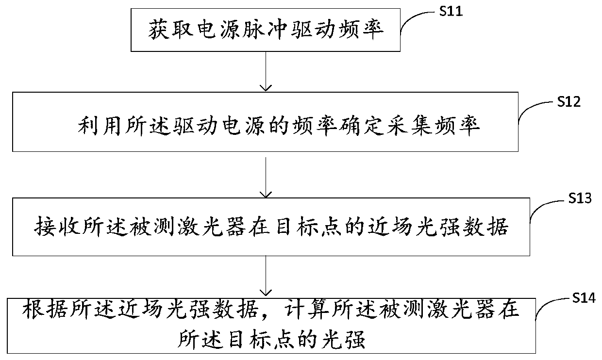
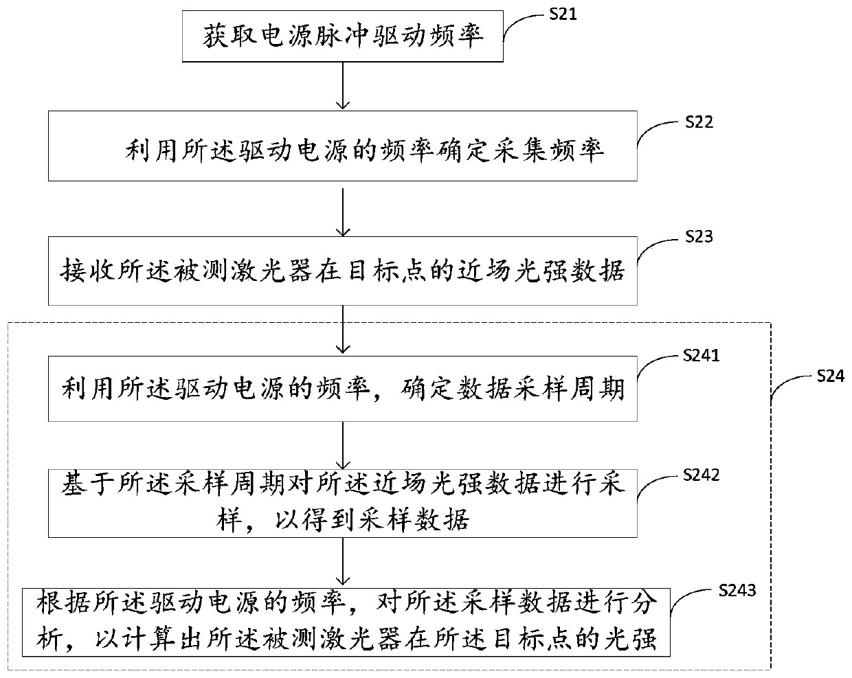
[0050] An embodiment of the present invention provides a laser near-field testing method, figure 1 It is a flow chart of a laser near-field testing method according to an embodiment of the present invention, such as figure 1 As shown, the process includes the following steps:

[0051] S11, acquiring the power pulse driving frequency.

[0052] Before the te...


PUM


Abstract

The invention relates to the field of laser characteristic testing, and specifically relates to a laser near-field testing method and system. The method comprises the steps that the frequency of a driving power source is obtained, wherein the driving power source is used for driving a tested laser to emit light; the frequency of the driving power source is used for determining the collection frequency; near-field light intensity data of the tested laser at a target point are received, wherein the near-field light intensity data are collected based on the collection frequency; according to thenear-field light intensity data, the light intensity of the tested laser at the target point is calculated. According to the method, it can be guaranteed that the output period of the tested laser isconsistent with the sampling period, the laser is in an output state during sampling, and therefore the testing accuracy is guaranteed.

Description

technical field [0001] The invention relates to the field of laser characteristic testing, in particular to a laser near-field testing method and testing system. Background technique [0002] Lasers are key devices in the fields of communication, computer, aerospace, medical and other fields, and the quality of lasers is determined by various parameters, among which the near field of light emission is an important parameter. Through the test of the near field of the laser light emission, information such as the uniformity of the active area, the position of the light emission and the current spread can be obtained. If it is possible to test the correspondence between the luminous near-field and the spectrum, it is possible to understand the change of the mode with the current. [0003] Among them, the near-field test of the laser usually uses a slit followed by a power meter or a photodetector to detect the relative position of the laser and the slit, and judge the intensit...

Claims


Application Information

Patent Timeline
Patent Type & Authority Applications(China)
IPC IPC(8): G01M11/02
CPCG01M11/02
Inventor 潘华东梁志敏周立王俊李泉灵廖新胜
Owner SUZHOU EVERBRIGHT PHOTONICS CO LTD
Why Eureka
Try Eureka