Light emitting device

a light-emitting device and light-emitting technology, which is applied in the direction of semiconductor devices, basic electric elements, electrical apparatus, etc., can solve the problems of insufficient light extraction efficiency, difficult to coat the vicinity of the light-emitting device without mismatching, and difficult to extract the light that is absorbed and lost by the base member and the conductive member, so as to achieve efficient reflected light and high light extraction efficiency

Active Publication Date: 2012-08-02
NICHIA CORP
View PDF19 Cites 42 Cited by
  • Summary
  • Abstract
  • Description
  • Claims
  • Application Information

AI Technical Summary

Benefits of technology

[0026]According to a support body and a light emitting device of the present invention, the light to be absorbed by the base member and conductive members can be efficiently reflected and extracted outside through a translucent member having a lens shape, and accordingly, the light emitting device having high light extraction efficiency can be obtained.

Problems solved by technology

Therefore, it is difficult to coat a vicinity of the light emitting device without mismatching, while the vicinity is the area that the light reflection is to be maximized.
However, if an additive amount of light reflective filler is such amount to allow that the resin may be coated and spread, the resin can not reflect the light and an absorption amount of the light by the base member is not small, thereby resulting in insufficient light extraction efficiency.
Even if a convex lens, such as the one described in Patent Documents 3, 4, is disposed in these light emitting devices, it is difficult to extract the light that is absorbed and lost by the base member and the conductive members.
Therefore, the effect of improvement of the light extraction efficiency by the lens is not sufficient, and accordingly, a further improvement of the light extraction efficiency is expected.

Method used


Image

  • Light emitting device
  • Light emitting device
  • Light emitting device

Examples


first embodiment

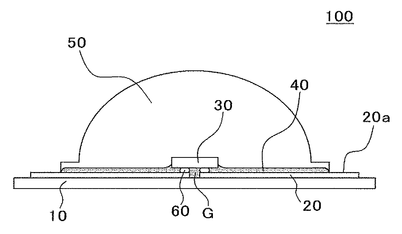
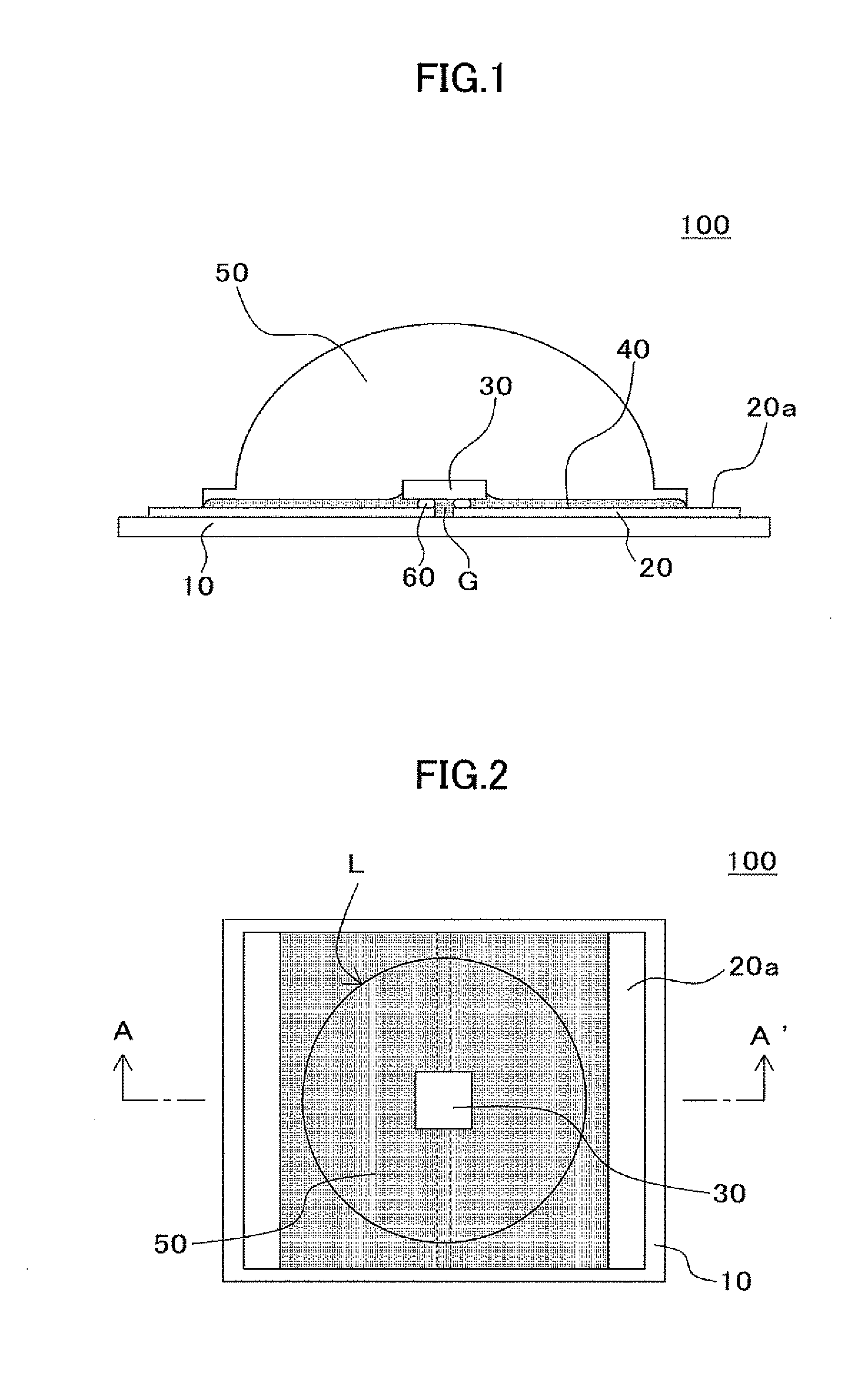
[0035]FIG. 1 is a cross sectional view showing a light emitting device 100 according to a first embodiment of the present invention. FIG. 2 is a plan view showing the light emitting device 100 of FIG. 1, and a cross sectional view taken along A-A′ line of FIG. 2 is sown FIG. 1.

[0036]The light emitting device 100 of the present embodiment mainly includes a base body 10, a conductive member 20, alight emitting element 30, an insulating filler 40 and a translucent member 50. A surface of the translucent member 50 is formed in a lens shape protruded upward.

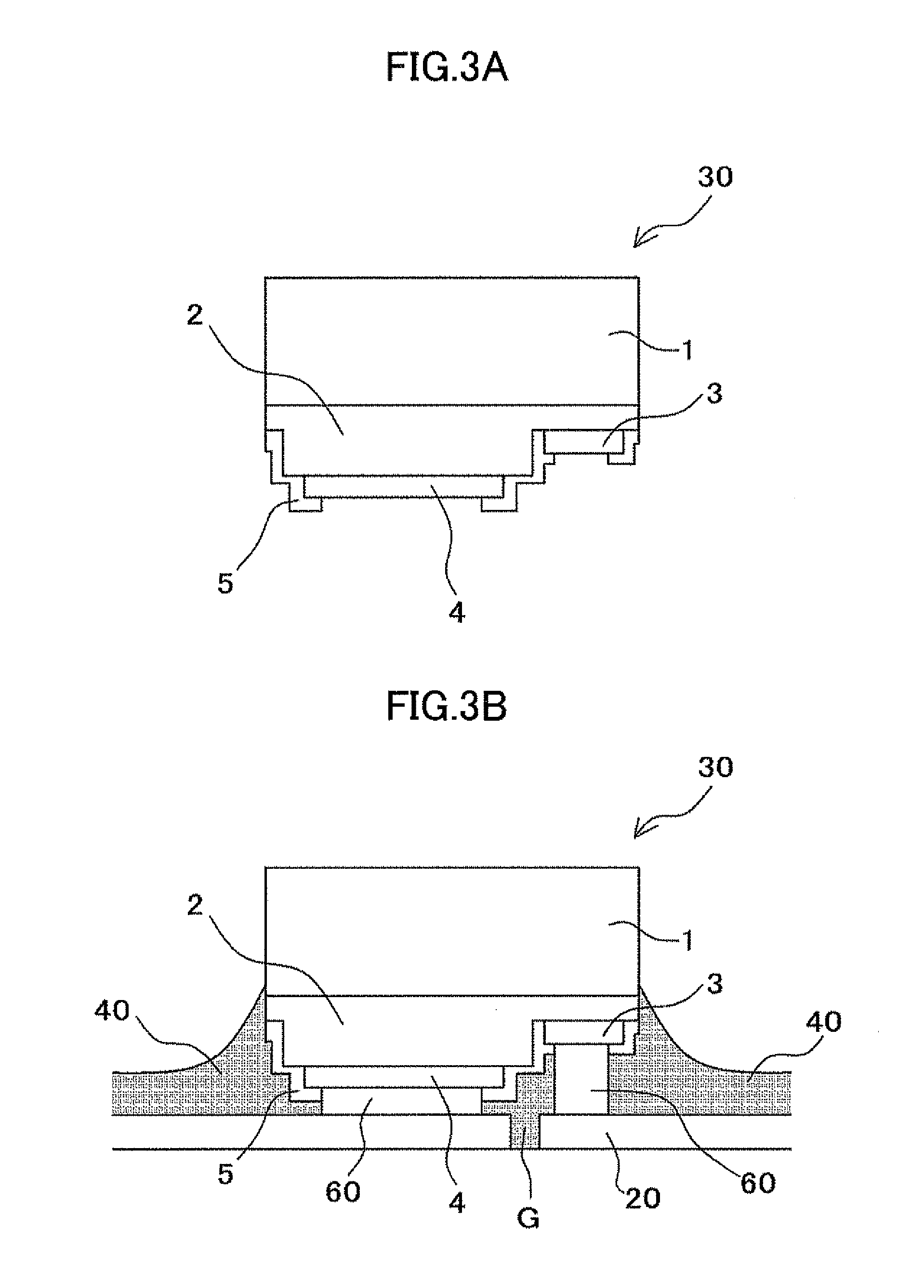
[0037]The base body 10 has a flat shape, and as shown in FIG. 2, is formed in a rectangular shape in plan view. A pair of conductive members 20 that are separated in a positive part and a negative part in the longitudinal direction are disposed on a main surface of the base body 10. The light emitting element 30 is placed on the conductive member 20 through a conductive bonding member 60 so as to bridge between the separated positive ...

second embodiment

[0120]In the present embodiment, explanation will be given of an example that arranges a fluorescent material around a light emitting element. The second embodiment is identical to the first embodiment except for the arrangement of the fluorescent material.

[0121]As shown in FIG. 4, a frame body 70 is disposed on a surface of the conductive member 20 apart from the light emitting element 30. The frame body 70 has a function to fill a fluorescent material-containing resin inside the frame and convert a wavelength of a light emitted from the light emitting element 30.

(Frame Body 70)

[0122]It is preferable that the frame body 70 is a member having a light reflecting function, and the member is preferably an insulating material that absorbs light very little and is resistant to light and heat. As a specific material, for example, silicone resin, epoxy resin and urea resin may be listed up. In addition, for example, a colorant, a light diffusion agent, filler and a fluorescent material may...

third embodiment

[0142]In the present embodiment, explanations will be given of an example where materials of a resin material with which the filler is impregnated and a translucent member to be formed into a lens shape are different to each other. The third embodiment is identical to the first embodiment except for the foregoing materials.

[0143]As shown in FIG. 5, in the present embodiment, the filler 40 is impregnated with the resin material 90, and the filler 40 is further covered by the translucent member 50.

(Resin Material 90)

[0144]The resin material 90 is a resin for filling spaces among filler 40. As a specific material, for example, silicone resin, epoxy resin and urea resin may be listed up.

[0145]It is preferable that a refractive index of the resin material 90 is set to be smaller than the refractive index of the translucent member 50 that is formed on the resin material 90. Then, a light having an incident angle more than a critical angle corresponding to a difference between refractive i...


PUM


Abstract

A light emitting device which includes: a base body; a conductive member disposed on the base body; a light emitting element placed on the conductive member; and a translucent member disposed above the light emitting element. A surface of the translucent member is formed in a lens shape, and when a portion formed in the lens shape of the translucent member on a surface of the conductive member is perspectively seen from above, an area other than a portion where the light emitting element is placed is coated with an insulating filler to form a light reflection layer.

Description

CROSS REFERENCE TO RELATED APPLICATIONS[0001]This application claims the foreign priority benefit under Title 35, United States Code, §119(a)-(d) of Japanese Patent Application Number 2011-16420, filed on Jan. 28, 2011, the contents of which are hereby incorporated by reference.BACKGROUND OF THE INVENTION[0002]1. Field of the Invention[0003]The present invention relates to a light emitting device which is applicable to, for example, a display device, lighting equipment, a display and a backlight source of a liquid crystal display.[0004]2. Description of the Related Art[0005]Recently, various kinds of electronic components have been proposed and put into practical use, and the performances required for these components have been also raised high. Especially, regarding the electronic components, the performances are required to be maintained for a long time under a severe environment of usage. The foregoing situation is the same for the light emitting device including a light emitting...

Claims


Application Information

Patent Timeline
Patent Type & Authority Applications(United States)
IPC IPC(8): H01L33/60
CPCH01L25/167H01L33/46H01L2224/32225H01L24/17H01L2224/73204H01L33/505H01L33/507H01L33/54H01L33/62H01L2924/12041H01L24/97H01L2224/16225H01L2924/01012H01L2924/01029H01L33/60H01L2924/00H01L2924/181H01L2924/12035H01L2924/12042
Inventor YAMADA, MOTOKAZU
Owner NICHIA CORP
Why Eureka
Try Eureka