
Target for surveying instrument

a technology of target and surveying instrument, which is applied in the direction of instruments, distance measurement, reference lines/planes/sectors, etc., can solve the problems of difficult to confirm when the transmitting light amount is low, and achieve the effect of improving working efficiency, improving working efficiency, and ensuring safety

Active Publication Date: 2006-10-31
KK TOPCON
View PDF8 Cites 42 Cited by
  • Summary
  • Abstract
  • Description
  • Claims
  • Application Information

AI Technical Summary

Benefits of technology

[0011]It is an object of the present invention to provide a target for a surveying instrument, by which it is possible to ensure a distance measuring light amount in a non-prism type surveying instrument with a coaxial laser point light, and the transmitting laser point light can be efficiently confirmed visually. Further, it is another object of the present invention to provide a target, by which it is possible to measure a longer distance by keeping stable distance measuring light amount.
[0013]According to the present invention, a target for a surveying instrument, which receives from the surveying instrument a laser point light indicating a position and a distance measuring light to measure a distance, comprises a reflection diffusion layer for reflecting and diffusing the distance measurement light, a wavelength filter layer for selectively transmitting the laser point light passing through the reflection diffusing layer, and a transmission diffusion layer for spreading in a given direction and for transmitting the laser point light passing through the wavelength filter layer, wherein a projecting position of the laser point light can be confirmed. As a result, even in case the non-prism type surveying instrument is used and two operators are required for the survey setting operation, the projecting point can be confirmed on the target side, and this contributes to the improvement of working efficiency.
[0014]Also, according to the present invention, in the target for a surveying instrument as described above, the transmission diffusion layer comprises a fiber array for spreading the transmitting light in a top-to-bottom direction. Thus, because the transmitting light is spread in a top-to-bottom direction, the projecting point of the laser point light can be confirmed even when the optical axis of the laser point light does not concur with a visual line of the operator, and this contributes to the improvement of working efficiency.
[0015]Further, according to the present invention, in the target for a surveying instrument as described above, the wavelength filter layer is a bandpass filter for transmitting a wavelength of the visible laser point light projected from the surveying instrument and for reflecting the distance measuring light. Because the distance measuring light does not pass through the target, safety is assured.
[0016]Also, according to the present invention, in the target for a surveying instrument as described above, the reflection diffusion layer is formed on a surface of the wavelength filter layer. This makes it possible to have simple arrangement, and it is possible to manufacture a target for surveying instrument at low cost.
[0017]Further, according to the present invention, in the target for a surveying instrument as described above, a fiber array is formed on a surface of the wavelength filter, and the fiber array is used as the transmission diffusion layer. This makes it possible to have simple arrangement and to have reflection of the distance measuring light effectively from the target.

Problems solved by technology

Because the laser point light can be visually confirmed when the laser point light is diffused and passes through, it is difficult to confirm when the transmitting light amount is low.

Method used


Image

  • Target for surveying instrument
  • Target for surveying instrument
  • Target for surveying instrument

Examples


Embodiment Construction

[0022]Description will be given below on the best mode of the invention for carrying out the present invention referring to the drawings.

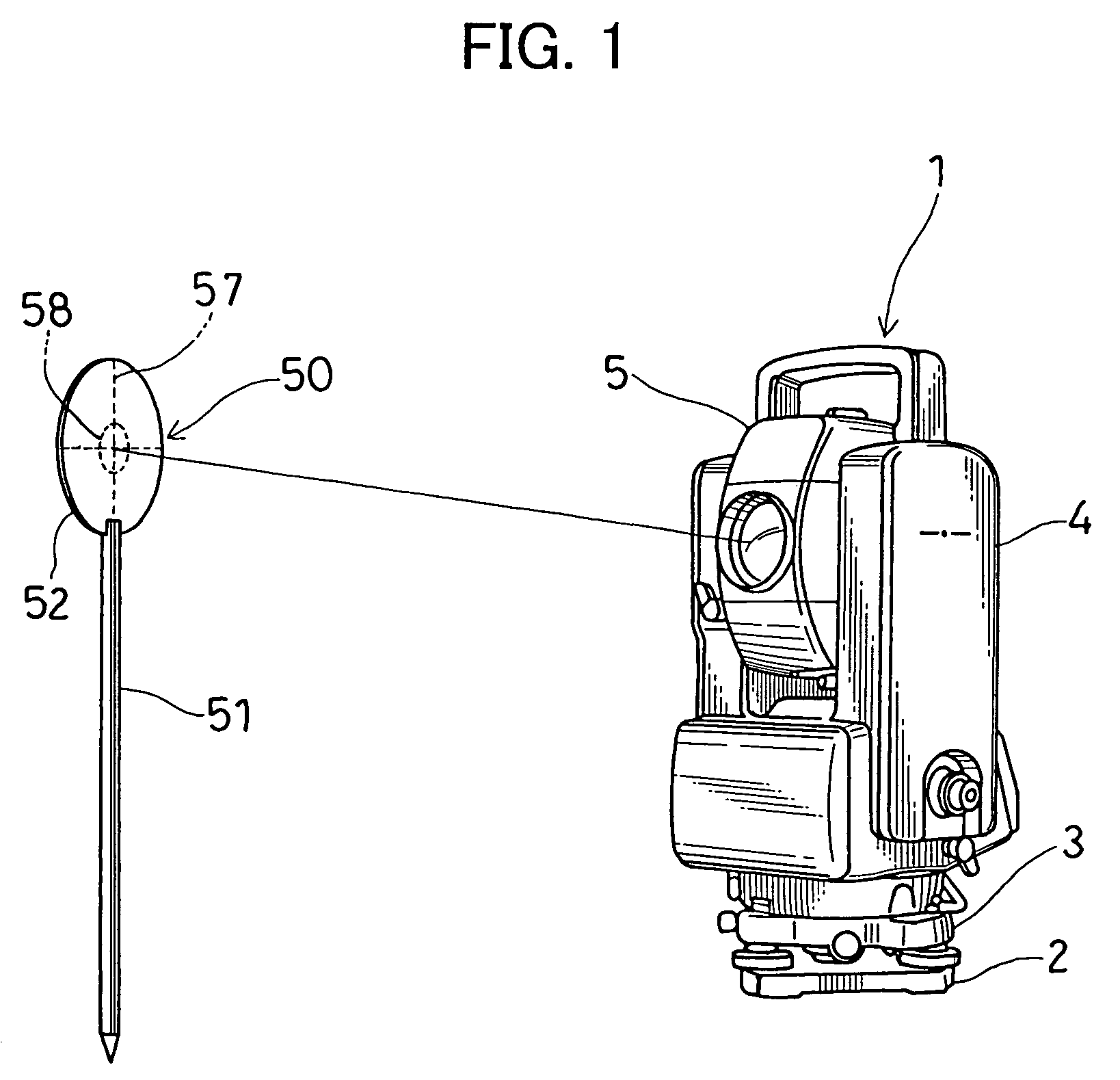
[0023]FIG. 1 represents a surveying instrument 1 and a target 50 according to the present invention.

[0024]The surveying instrument 1 comprises a leveling unit 2 mounted on a tripod (not shown in the drawings), a base unit 3 mounted on the leveling unit 2, a frame unit 4 rotatably mounted around a vertical axis on the base unit 3, and a telescope unit 5 rotatably mounted around a horizontal axis on the frame unit 4. An optical system to be described later is accommodated in the telescope unit 5.

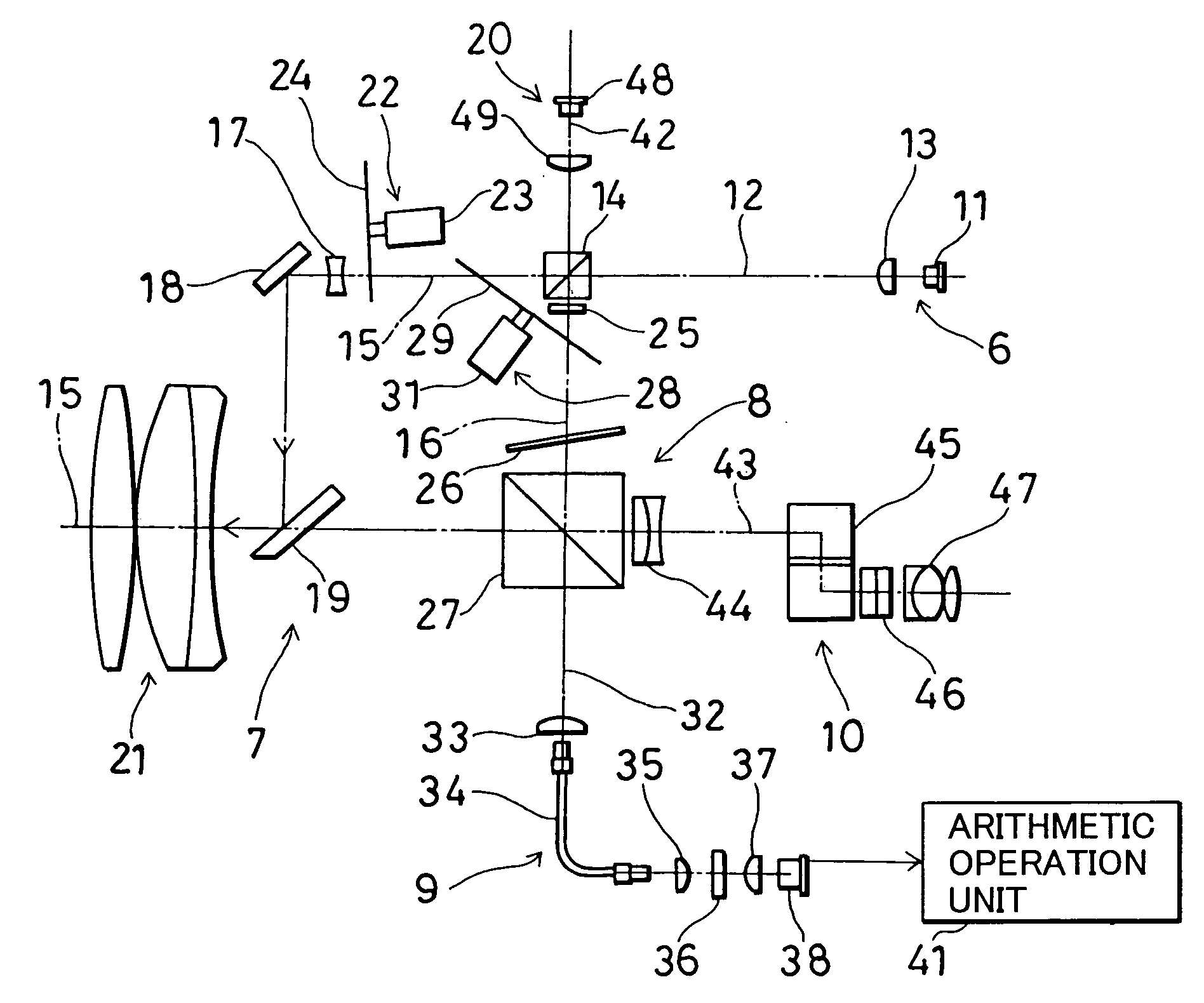
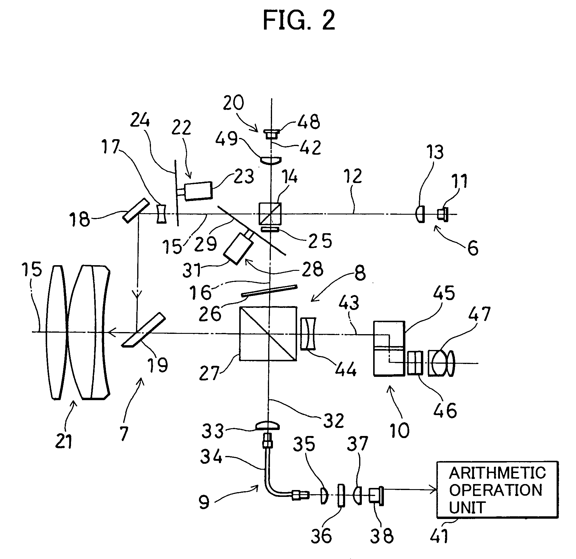
[0025]First, description will be given on a non-prism type surveying instrument to be used in the present invention referring to FIG. 2.

[0026]In the figure, reference numeral 6 represents a light source unit, 7 represents a projection optical system, 8 represents an internal reference optical system, 9 represents a photodetection optical system, 10 represents...


PUM


Abstract

A target for a surveying instrument, which receives from the surveying instrument a laser point light indicating a position and a distance measuring light to measure a distance, comprising a reflection diffusion layer for reflecting and diffusing the distance measuring light, a wavelength filter layer for selectively transmitting the laser point light passing through the reflection diffusion layer, and a transmission diffusion layer for spreading in a given direction and for transmitting the laser point light passing through the wavelength filter layer, wherein a projecting position of the laser point light can be confirmed.

Description

BACKGROUND OF THE INVENTION[0001]The present invention relates to a surveying operation guidance system for providing guidance for an operator, who engages in surveying operation, e.g. for determination of a survey setting point, etc.[0002]In a surveying operation, e.g. in a survey setting operation, an operator who operates on a surveying instrument installed at a known point (hereinafter referred as “distance measuring operator”), measures a target position for an operator on a target side (hereinafter referred as “pile driving operator”), and provides guidance the pile driving operator to move to a survey setting point (pile driving point). The position of the target is set at the survey setting point, and a pile is driven. Thus, survey setting operation requires two operators, i.e. the distance measuring operator and the pile driving operator.[0003]As the surveying instrument, a surveying instrument of prism measurement type, using a prism mounted on a pole as a target, is now w...

Claims


Application Information

Patent Timeline
Patent Type & Authority Patents(United States)
IPC IPC(8): G01B11/26G01C1/00
CPCG01C15/006
Inventor OHTOMO, FUMIOKODAIRA, JUN-ICHI
Owner KK TOPCON
Learn More