Fixing and clamping device for transformer box

A fixed clamping and transformer box technology, applied in the field of transformer box, can solve the problems of poor fixing effect and unstable transformer box, etc., and achieve the effect of simple structure and obvious fixing effect

Active Publication Date: 2017-01-04
优尼斯工业服务(徐州)有限公司
View PDF4 Cites 8 Cited by
  • Summary
  • Abstract
  • Description
  • Claims
  • Application Information

AI Technical Summary

Problems solved by technology

[0004] The purpose of the present invention is to provide a fixed clamping device for a transformer box, which has the advantage of obvious fixing effect and solves the problems of unstable transformer box and poor fixing effect

Method used


Image

  • Fixing and clamping device for transformer box
  • Fixing and clamping device for transformer box

Examples


Embodiment Construction

[0016] The following will clearly and completely describe the technical solutions in the embodiments of the present invention with reference to the accompanying drawings in the embodiments of the present invention. Obviously, the described embodiments are only some of the embodiments of the present invention, not all of them. Based on the embodiments of the present invention, all other embodiments obtained by persons of ordinary skill in the art without making creative efforts belong to the protection scope of the present invention.

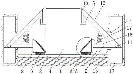
[0017] see Figure 1-2 , a fixed clamping device for a transformer box, including a base 1, a slide rail 2 is fixedly connected to the upper surface of the base 1, and two sliders 3 are slidably connected to the inside of the slide rail 2, through the connection between the slide rail 2 and the slider 3 Cooperate with the use, so that the slider 3 can move in the slide rail 2, and the transformer box 4 is placed between the two sliders 3, and the...


PUM


Abstract

The invention discloses a fixing and clamping device for a transformer box. The fixing and clamping device comprises a base. A sliding rail is fixedly connected to the upper surface of the base. Two sliding blocks are connected to the interior of the sliding rail in a sliding mode. The transformer box is placed between the two sliding blocks. The two sides of the transformer box are provided with L-shaped hooks. The tops of the sliding blocks are fixedly connected with the bottoms of two triangular plates. The inclined faces of the two triangular plates are each provided with a first pulley. The right angle sides of the triangular plates are fixedly connected with one side of a fixing plate. The transformer box is improved, due to cooperation of the sliding rail, the sliding blocks, the triangular plates, the first pulleys and the transformer box, under the pressure of the transformer box, the triangular plates and the first pulleys move back to back, and therefore the sliding blocks are driven to slide left and right inside the sliding rail; due to cooperation of the fixing plate, a through hole and a second pulley, the fixing plate is effectively limited, and therefore the bottom end of the transformer box is fixed and clamped, and the fixing and clamping effects are achieved.

Description

technical field [0001] The invention relates to the technical field of transformer boxes, in particular to a fixing and clamping device for a transformer box. Background technique [0002] The substation box is the box in the place where the voltage and current of the electric energy are transformed, concentrated and distributed. The flow direction and distribution of voltage, current and power in each node and branch in the network) control and protection of transmission and distribution lines and main electrical equipment. [0003] During the transportation of the transformer box, due to the rough road, the transformer box is swinging and unstable, and the connection between the iron core of the transformer box and the output end of the transformer box is easy to be loose. The stabilization effect of the existing transformer box is poor, and it is easy to Destroy the connection of the inner coil of the transformer, resulting in loose connection, causing leakage and econom...

Claims


Application Information

Patent Timeline
Patent Type & Authority Applications(China)
IPC IPC(8): H02B1/46H02B1/50
CPCH02B1/46H02B1/505
Inventor 计照明
Owner 优尼斯工业服务(徐州)有限公司
Why Eureka
Try Eureka