Overvoltage protection circuit and overvoltage protection method for wireless charging receiving end

An overvoltage protection circuit and wireless charging technology, which is applied to battery circuit devices, circuit devices, current collectors, etc., can solve problems such as failure of protection devices, energy consumption of protection devices, and limited protection effect, so as to solve the problem of function failure and improve over-voltage protection. The effect of pressure protection and the effect of solving energy loss

Inactive Publication Date: 2017-01-04
GEER TECH CO LTD
View PDF6 Cites 6 Cited by
  • Summary
  • Abstract
  • Description
  • Claims
  • Application Information

AI Technical Summary

Problems solved by technology

However, this overvoltage protection method is realized by the energy consumption of the protection device. After a long-term operation, the protection device may fail, so the protection effect is very limited.

Method used


Image

  • Overvoltage protection circuit and overvoltage protection method for wireless charging receiving end
  • Overvoltage protection circuit and overvoltage protection method for wireless charging receiving end
  • Overvoltage protection circuit and overvoltage protection method for wireless charging receiving end

Examples


Embodiment Construction

[0023] The specific implementation manners of the present invention will be further described in detail below in conjunction with the accompanying drawings.

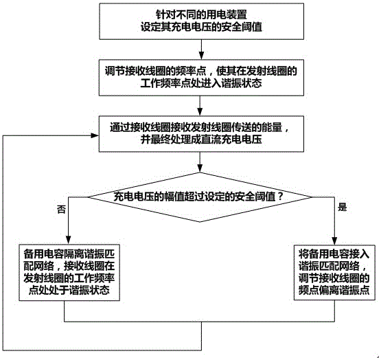
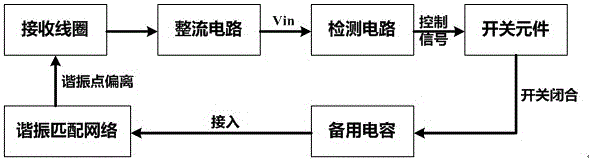
[0024] This embodiment proposes an overvoltage protection method based on the resonant wireless charging technology, which is applied to the receiving end of the wireless charging system. When the voltage of the receiving coil is too high, the frequency point of the receiving coil can be automatically adjusted to deviate from the working frequency of the transmitting coil. Point, by controlling the receiving coil to enter the mismatch state, the voltage of the receiving coil is reduced, and then the design purpose of overvoltage protection is achieved.

[0025] Its specific implementation method is as follows: combining figure 1 As shown, firstly, the safety threshold is set in advance according to the bearing capacity of different electric devices to the charging voltage. According to the set safety threshold, the oper...


PUM


Abstract

The invention discloses an overvoltage protection circuit and overvoltage protection method for a wireless charging receiving end. The circuit comprises a receiving coil which receives in a resonance mode energy transmitted by a transmitting coil and converts the energy into an alternating voltage; a resonance matching network which is connected with the receiving coil and is used for adjusting the frequency of the receiving coil; a rectifying circuit which is used for carrying out rectification conversion on the alternating voltage to generate a direct current charging voltage; and a detection circuit. The detection circuit detects the amplitude of the direct current charging voltage and compares the amplitude with a set safety threshold. If the amplitude of the charging voltage exceeds the set safety threshold, the resonance matching network is controlled to adjust the working frequency of the receiving coil, so that the working frequency point of the receiving coil at the transmitting coil is in an unresonance state, the voltage received by the receiving coil is reduced, and a design purpose of carrying out overvoltage protection on the receiving end is realized. The circuit and the method are simple in design and reliable in work. The charging safety of a power utilization device is greatly improved.

Description

technical field [0001] The invention belongs to the technical field of wireless charging, and in particular relates to a circuit design and implementation method for overvoltage protection of a receiving end in a wireless charging system. Background technique [0002] Wireless charging technology is derived from wireless energy transmission technology. Low-power wireless charging technology often adopts electromagnetic induction, while high-power wireless charging technology uses resonance, and the power supply equipment (charger) transmits energy to the electrical device. The powered device uses the received energy to charge its internal battery and at the same time for its own operation. Since energy is transmitted between the charger and the electric device by a magnetic field, there is no need for a wire connection between the two. Therefore, both the charger and the electric device can have no exposed conductive contacts, which has high safety, and the charging operatio...

Claims


Application Information

Patent Timeline
Patent Type & Authority Applications(China)
IPC IPC(8): H02J7/00H02J50/12
CPCH02J7/025
Inventor 孙树波
Owner GEER TECH CO LTD
Why Eureka
Try Eureka