
Charging circuit and charging method thereof and terminal

A charging circuit and charging voltage technology, applied in the electronic field, can solve problems such as large ripple current, charging path loss, and reduced efficiency of charging chips, and achieve the effect of weakening ripple interference and reducing ripple current

Active Publication Date: 2017-01-04
SHENZHEN TRANSSION HLDG CO LTD
View PDF3 Cites 6 Cited by
  • Summary
  • Abstract
  • Description
  • Claims
  • Application Information

AI Technical Summary

Problems solved by technology

However, since the charging current of terminals currently on the market has reached 4 amperes when using a single charging chip to achieve high-current charging, such a large charging current will inevitably cause a large loss in the charging path, and the ripple current is large and the charging The efficiency of the chip is reduced and it causes great interference to surrounding chips (such as cameras, radio frequency devices, antennas, etc.); the second method is to use two charging chips in parallel on the terminal to achieve high-current charging
However, although this method can reduce the charging current of each charging path, thereby reducing the loss of the charging path, since the two charging chips in this method are independently controlled, they will also be in the same phase or at different frequencies. Generate a large ripple current, and also cause interference to surrounding ripple-sensitive devices
[0004] To sum up, the existing terminal charging method has the problems of large ripple current and strong interference

Method used


Image

  • Charging circuit and charging method thereof and terminal
  • Charging circuit and charging method thereof and terminal
  • Charging circuit and charging method thereof and terminal

Examples


Embodiment Construction

[0024] The following will clearly and completely describe the technical solutions in the embodiments of the present invention with reference to the accompanying drawings in the embodiments of the present invention. Obviously, the described embodiments are some of the embodiments of the present invention, but not all of them. Based on the embodiments of the present invention, all other embodiments obtained by persons of ordinary skill in the art without making creative efforts belong to the protection scope of the present invention.

[0025] It should be understood that when used in this specification and the appended claims, the term "comprising" indicates the presence of described features, integers, steps, operations, elements and / or components, but does not exclude one or more other features. , whole, step, operation, element, component and / or the presence or addition of a collection thereof.

[0026] It should also be understood that the terminology used in the description...


PUM


Abstract

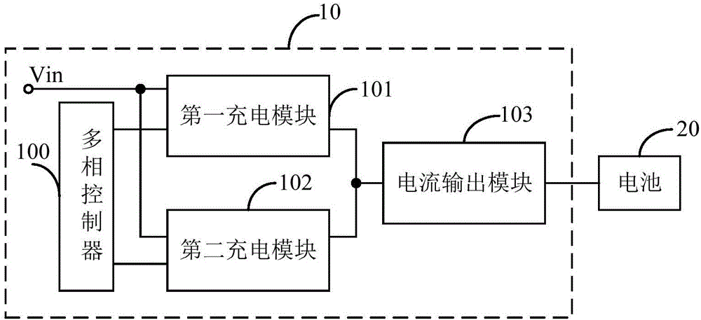
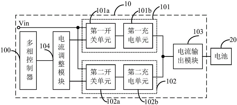
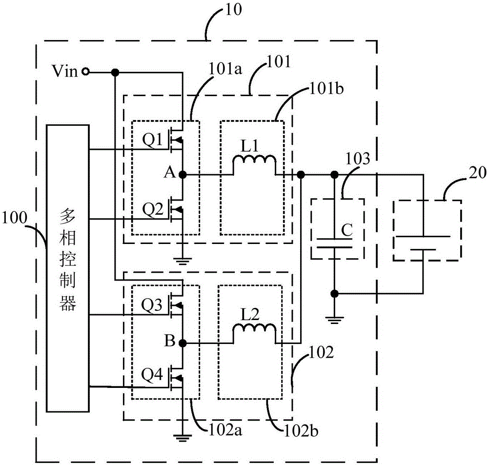
The embodiment of the invention discloses a charging circuit and a charging method thereof and a terminal. The charging circuit comprises a multi-phase controller, a first charging module, a second charging module and a current output module, wherein the multi-phase controller outputs a first control command to the first charging module and simultaneously outputs a second control command to the second charging module; the first charging module and the second charging module receive the same input voltage; the first charging module outputs first current according to the first control command and the input voltage; the second charging module outputs second current according to the second control command and the input voltage; and the current output module superimposes the first current and the second current and then charges a battery. The charging circuit disclosed by the embodiment of the invention is small in ripple current and ripple interference is weak.

Description

technical field [0001] The invention relates to the field of electronic technology, in particular to a charging circuit, a charging method and a terminal thereof. Background technique [0002] With the development of mobile communication technology, mobile phones, as a mobile portable device, have more and more functions and applications. In many occasions, such as playing games and watching videos online, mobile phones consume a lot of power. Therefore, increasing the charging current of mobile phones and shortening the charging time is one of the urgent needs of users. [0003] At present, the prior art mainly adopts two methods to solve the above problems. The first method is to use a single charging chip on the terminal to realize high-current charging. However, since the charging current of terminals currently on the market has reached 4 amps when using a single charging chip to achieve high-current charging, such a large charging current will inevitably cause a large...

Claims


Application Information

Patent Timeline
IPC IPC(8): H02J7/00
CPCH02J7/007
Inventor 陈泰傧
Owner SHENZHEN TRANSSION HLDG CO LTD
Learn More