
Multi Output Inverter

Active Publication Date: 2010-12-23
POWER CONCEPTS NZ
View PDF25 Cites 35 Cited by
  • Summary
  • Abstract
  • Description
  • Claims
  • Application Information

AI Technical Summary

Benefits of technology

[0009]Preferably the phase controller is adapted to alter the phase of the AC output voltages on one or more of the output channels of the DC to AC inverter b

Problems solved by technology

The magnitude of the DC current needed to supply these larger inverters is becoming problematic.
In vessels there are many motor driven pieces of equipment that could be advantageously driven by motor speed controllers, but the use of dedicated motor speed controllers has been restricted by cost.
In most commercially available inverters the reservoir capacitor is not large enough to materially reduce the mains frequency related AC component drawn from the DC supply.
Ripple voltage can cause a number of problems in other equipment connected to the same energy store.
Some audio equipment is susceptible to ripple voltage on its supply connection and will produce audible interference at the ripple frequency.
If the ripple voltage is large enough, the voltage dips corresponding to the peaks in the current waveform may be low enough to trip the under-voltage detect function of some electronic equipment, causing the equipment to reset.
There are various wear-out mechanisms that limit the number of times that the lead compounds can transition between their charged and discharged states, so the tendency for the reactions to occur preferentially in a portion of the lead compounds results in a reduced cell life.
Almost all cell chemistries involve reactions between solid active materials and a liquid electrolyte and so are highly likely to show the same kind of reduction in life when subjected to high ripple currents.
One of the problems associated with these alternators is the generation of a “load dump” transient over-voltage if the energy store is disconnected from the alternator while the alternator is supplying a significant current.
Many electronic products on the market are not designed to withstand this type of over-voltage event.
This is no simple task because of the large amount of energy involved.
This type of motor has many problems, such as the need to regularly maintain and replace the brushes, the size and weight of the supply cables, the high weight of the motor, the high turn on current surge, the high start up acceleration of the motor, the sensitivity to voltage drops, and fixed speed operation.

Method used


Image

  • Multi Output Inverter
  • Multi Output Inverter
  • Multi Output Inverter

Examples


Embodiment Construction

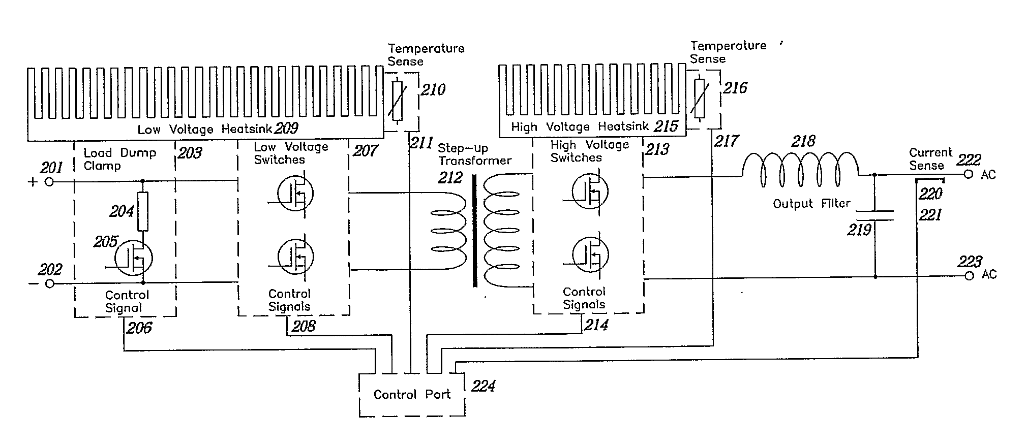
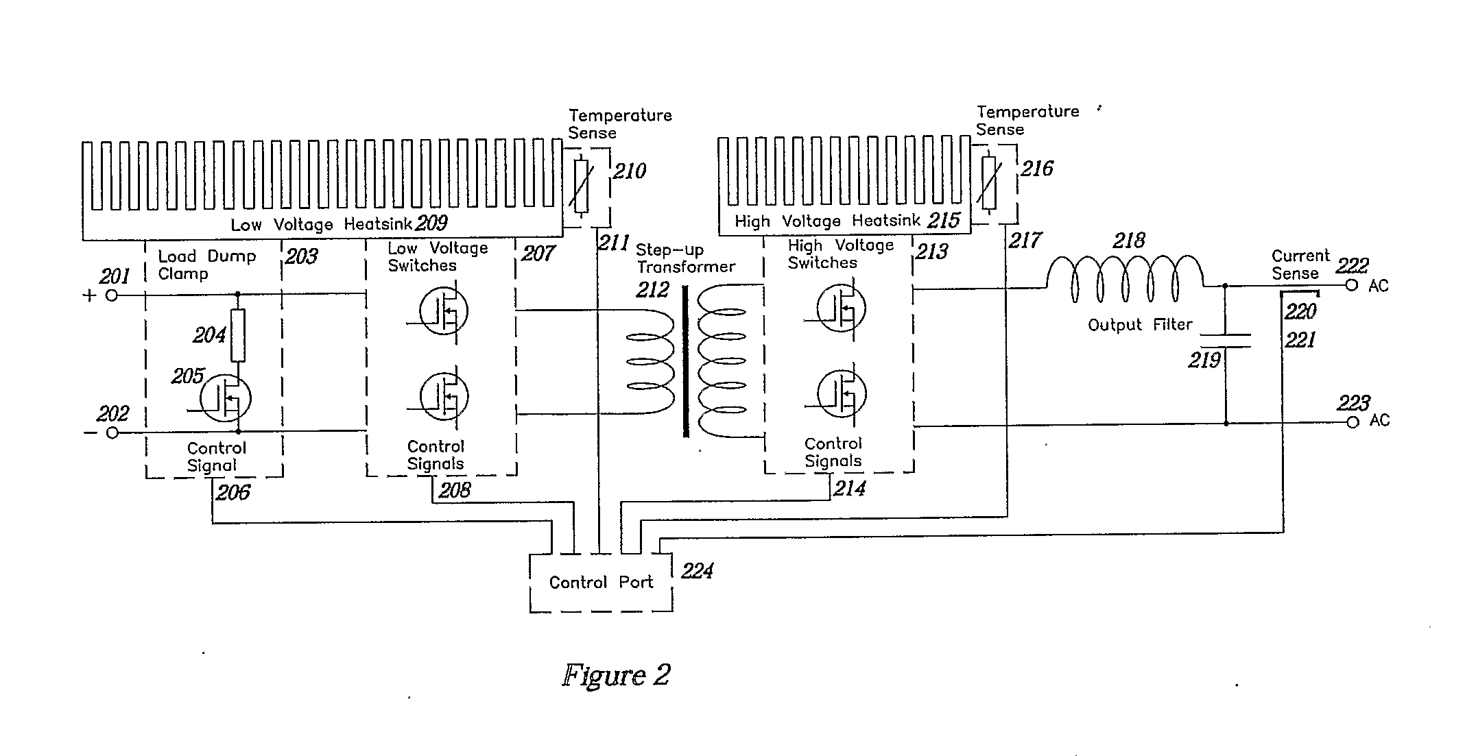
[0048]The present invention provides a multiple output DC to AC inverter that can dynamically consolidate and split output channels to provide for load requirements (including poly-phase motors) while minimising DC power current demands, and dynamically alter phase / frequency of channels to minimise ripple current.

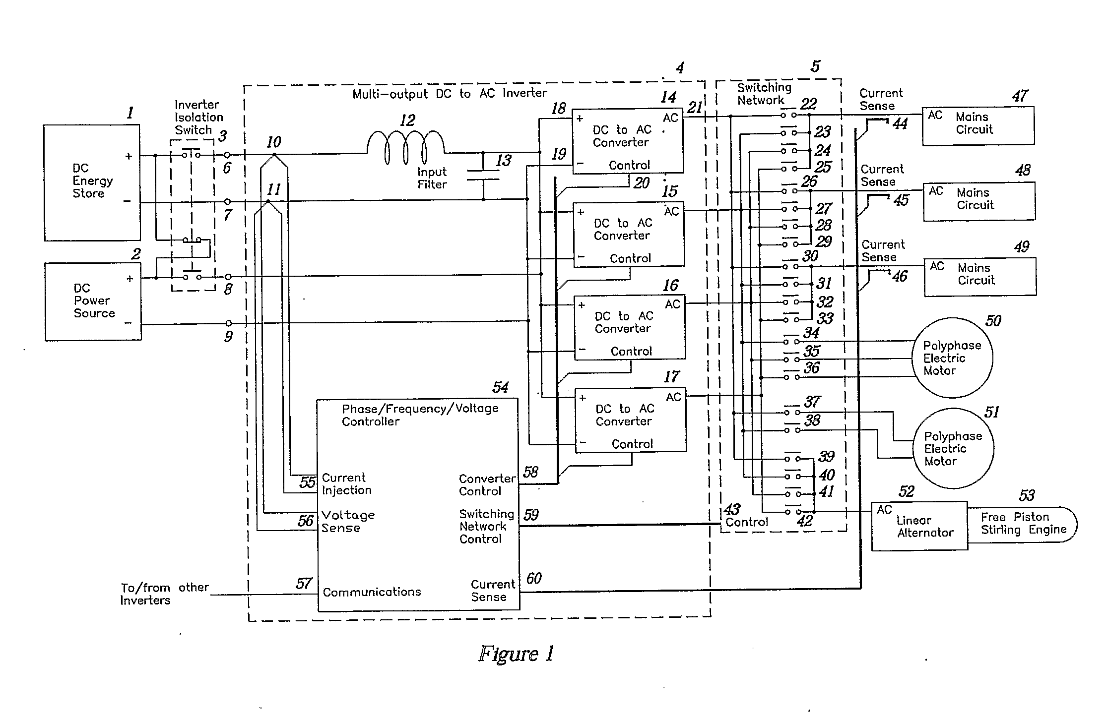
[0049]Referring to FIG. 1, a long term DC energy store 1 connects via an inverter isolation switch 3 to the positive input terminal 6 and the negative input terminal 7 of a multi-output DC to AC inverter 4. Conductors inside the inverter connect from the positive and negative input terminals to an input filter consisting of an inductor 12 and a reservoir capacitor 13. The inductor may be connected in series with one of the input conductors as shown or may be split with some inductance in series with the positive conductor and some in series with the negative conductor. All or part of the input filter inductance may be formed from the self inductance of the cables between th...


PUM


Abstract

The present invention relates to a multi output inverter that is adapted to supply mains powered appliances (47-49) and / or poly-phase motors (50, 51). The inverter is also adapted to reduce ripple current.

Description

FIELD OF THE INVENTION[0001]This present invention relates to DC to AC inverters for supplying mains power apparatus and / or poly-phase motors.BACKGROUND TO THE INVENTION[0002]Larger DC to AC inverters are coming into general use. The magnitude of the DC current needed to supply these larger inverters is becoming problematic. In vessels there are many motor driven pieces of equipment that could be advantageously driven by motor speed controllers, but the use of dedicated motor speed controllers has been restricted by cost.[0003]An inverter producing 50 or 60 Hz sine-wave mains power will draw current from its DC supply in the form of a sine squared waveform with the peaks repeating at a rate of 100 or 120 Hz. For an ideal inverter with no losses, the peak current will be twice the average current and the minimum current will be zero. This is equivalent to a DC current flow (equal to the average current) with a large AC current superimposed on it. The peak-to-peak amplitude of the AC ...

Claims


Application Information

Patent Timeline
IPC IPC(8): H02P6/14H02M7/537H02J3/14
CPCH02M7/48H02M7/493H02M2001/008H02P27/08H02M7/4807H02J1/10H02M1/14H02M1/44H02M7/797H02M2001/322H02M1/126H02M1/008H02M1/322H02J3/007H02J3/34H02P5/74H02P23/00
Inventor FOTHERBY, CHRISTOPHER WILLIAM
Owner POWER CONCEPTS NZ
Learn More