Method for controlling boost-buck of motor driving Z-source inverter of electric automobile

A technology of motor drive and source inverter, which is applied in the direction of AC motor control, electric vehicles, motors, etc., can solve the problems of output current distortion, current ripple amplitude increase, and no buck-boost, etc. Effects of small voltage and current stress, reduced through-duty cycle, and reduced ripple current

Active Publication Date: 2019-09-24
HUNAN UNIV
View PDF4 Cites 0 Cited by
  • Summary
  • Abstract
  • Description
  • Claims
  • Application Information

AI Technical Summary

Problems solved by technology

However, the two-level structure of Solution 1 makes the energy conversion efficiency low. At the same time, in order to prevent the upper and lower bridge arms of the inverter bridge from being "through" and damage the power module, a dead time is usually added, which will cause distortion of the output current and affect the driving of electric vehicles. Performance; in Scheme 2, electric vehicles have different r

Method used


Image

  • Method for controlling boost-buck of motor driving Z-source inverter of electric automobile
  • Method for controlling boost-buck of motor driving Z-source inverter of electric automobile
  • Method for controlling boost-buck of motor driving Z-source inverter of electric automobile

Examples


Example Embodiment

[0056] The specific embodiments of the present invention will be described in further detail below in conjunction with the drawings and embodiments. The following examples are used to illustrate the present invention, but not to limit the scope of the present invention.
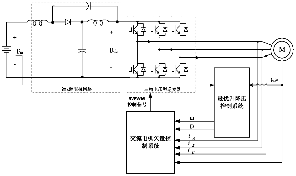
[0057] The embodiment of the present invention takes a quasi-Z source inverter to drive an AC motor as an example, such as figure 1 As shown, it includes a quasi-Z-source inverter composed of a battery, a quasi-Z-source impedance network and a three-phase voltage inverter, a motor, an AC motor vector control system and an optimal buck-boost control system; the battery passes through the quasi-Z source After the inverter is converted, it supplies power to the motor. The optimal buck-boost control system collects motor information, generates an optimal buck-boost control signal and transmits it to the AC motor vector control system. The AC motor vector control system is based on the motor information and the optim...


PUM


Abstract

The invention relates to the field of inverters, and relates to a method for controlling the boost-buck of a Z-source inverter of an electric automobile. The method comprises the steps of determining a required motor line voltage reference value by acquiring information, judging whether a straight-through signal is added to the system or not, and obtaining a corresponding modulation coefficient reference value and a corresponding straight-through duty ratio reference value, then adjusting the modulation coefficient and the straight-through duty ratio in a stepping way until the optimal modulation signal is reached to lead the system to reach the optimum, thereby solving the problems that the power supply voltage of a storage battery of the electric automobile is unstable, the energy conversion efficiency of the existing boosting solution is low, and the performance of a motor driving system is influenced or the problem of large inverter loss because the voltage requirement is not regulated and controlled according to different operating conditions of the electric automobile. The voltage can be boosted and reduced by using a quasi-Z-source inverter according to different requirements of the vehicle for the AC output voltage of the driving system under different operating conditions, and an optimal control method meeting the voltage requirements of the operating conditions is provided, so that the performance and efficiency of the driving system are optimally regulated and controlled.

Description

technical field [0001] The invention relates to the technical field of inverters, in particular to a buck-boost control method for a Z-source inverter used for driving an electric vehicle motor. Background technique [0002] The speed range of electric vehicle driving motor is very wide, which requires the power supply voltage of the motor to vary in a wide range. Moreover, when the electric vehicle is in frequent starting, accelerating and overtaking conditions, the battery will be discharged with a large current instantaneously, causing the battery output terminal voltage (drive system input voltage) to fluctuate sharply, and the battery terminal voltage will also decrease with the remaining battery power. Therefore, the fluctuation and gradual drop of the battery supply voltage bring great challenges to the motor drive system and will deteriorate the operating performance of electric vehicles. In order to solve these problems, there are currently two main solutions. One ...

Claims


Application Information

Patent Timeline
IPC IPC(8): H02P27/12H02M7/5395B60L15/20
CPCB60L15/2009B60L15/2063H02M7/5395H02P27/12Y02T10/64Y02T10/72
Inventor 刘平彭文书黄守道何敏杰
Owner HUNAN UNIV
Why Eureka
Try Eureka