DC chopping and boosting circuit

A booster circuit and DC chopper technology, applied in the direction of converting DC power input to DC power output, electrical components, adjusting electrical variables, etc., can solve the problems of large volume and weight of inductance, large ripple current, large peak current, etc. Achieve the effect of reducing volume and weight, reducing ripple current, and reducing capacitance

Inactive Publication Date: 2016-02-24
长沙丹芬瑞电气技术有限公司
View PDF4 Cites 0 Cited by
  • Summary
  • Abstract
  • Description
  • Claims
  • Application Information

AI Technical Summary

Problems solved by technology

[0003] 1. The current all passes through the inductor and diode, and the peak current is extremely large, that is, the input and output ripple current is very large, resulting in a large electrical stress on the output filter capacitor;
[0004] 2. In order to be able to output the required rated power, the volume and weight of t

Method used


Image

  • DC chopping and boosting circuit
  • DC chopping and boosting circuit
  • DC chopping and boosting circuit

Examples


Example Embodiment

[0014] The technical solutions in the embodiments of the present invention will be clearly and completely described below in conjunction with the accompanying drawings in the embodiments of the present invention. Obviously, the described embodiments are only a part of the embodiments of the present invention, rather than all the embodiments. Based on the embodiments of the present invention, all other embodiments obtained by those of ordinary skill in the art without creative work shall fall within the protection scope of the present invention.
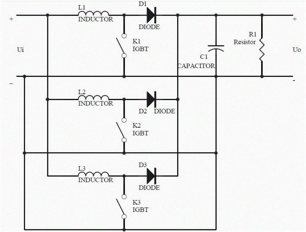
[0015] See image 3 , The present invention provides a DC chopper boost circuit, including three parallel channels, the first channel formed by inductor L1 and diode D1, the second channel formed by inductor L2 and diode D2, inductor L3 and diode D3 The third channel; each channel is connected in series with a load resistor R1 to form a loop, and a capacitor C1 is connected in parallel with the load resistor.

[0016] See image 3 , The th...


PUM


Abstract

The invention discloses a DC chopping and boosting circuit, which comprises three channels arranged in parallel, wherein each channel comprises an inductor and a diode; each channel is connected with a load resistor in series to form a loop, and the on-off of each channel is controlled through a switching tube; and the load resistor is connected with a capacitor in parallel. The DC chopping and boosting circuit breaks through the restriction of power size and frequency of the switching tubes, solves the difficulty of heat dissipation since the three channels are parallelly connected and dissipate heat in a distributed manner, further reduces ripple current of total input and output since each channel provides 1/3 power and the average current of each channel is 1/3 of the total current, reduces designed capacitance of the capacitor accordingly, prolongs the service life of the whole device, and reduces size and weight.

Description

technical field [0001] The invention relates to a telephone structure, in particular to a DC chopper boost circuit. Background technique [0002] The common step-up chopper circuit and the switching tube are as follows: figure 1 with figure 2 As shown, the single-channel working mode is adopted. When the switch tube K is closed, the inductor L stores electric energy, and when the switch tube K is turned off, the inductor L charges the output capacitor C through the diode D, and boosts the output. This circuit has the following disadvantages: [0003] 1. The current all passes through the inductor and diode, and the peak current is extremely large, that is, the input and output ripple current is very large, resulting in a large electrical stress on the output filter capacitor; [0004] 2. In order to be able to output the required rated power, the volume and weight of the inductor is generally very large (due to the limitation of IGBT / MOSFET power devices and diodes, in ...

Claims


Application Information

Patent Timeline
IPC IPC(8): H02M3/156H02M1/14H05K7/20
CPCH02M3/156H02M1/14H05K7/20
Inventor 陈卓吾
Owner 长沙丹芬瑞电气技术有限公司
Why Eureka
Try Eureka