
Electronic water pump and new energy automobile with electronic water pump

A technology of electronic water pump and pin insertion, which is applied to parts, pumps, and pump devices of elastic fluid pumping devices, and can solve problems such as easy water leakage, poor heat dissipation of electronic water pumps, and difficult assembly of electrical interfaces, etc., to achieve The effect of firm installation, good waterproof effect and low cost

Pending Publication Date: 2019-01-04
单志友
View PDF6 Cites 3 Cited by
  • Summary
  • Abstract
  • Description
  • Claims
  • Application Information

AI Technical Summary

Problems solved by technology

[0005] Aiming at the deficiencies of the prior art, the present invention provides an electronic water pump and a new energy vehicle with the electronic water pump. Through the assembly of the pin assembly, the gasket and the rear cover, the assembly of the electrical interface can be completed in a simple manner. In addition, the sealing gasket and the back cover are used to improve the sealing performance of the interface, which solves the problem that the electrical interface is not easy to assemble and is prone to water leakage; The heat dissipation ribs effectively solve the problem of poor heat dissipation of electronic water pumps that is common in the industry

Method used


Image

  • Electronic water pump and new energy automobile with electronic water pump
  • Electronic water pump and new energy automobile with electronic water pump
  • Electronic water pump and new energy automobile with electronic water pump

Examples


Embodiment 1

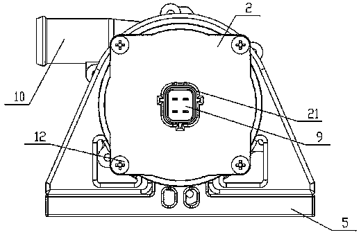
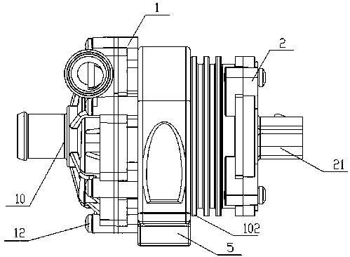
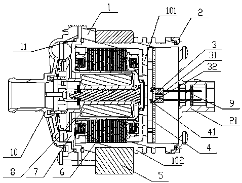
[0030] Such as figure 1 , 2 As shown in . Stator assembly 6, controller 4, screws 12, sealing ring 11, back cover 2, sealing gasket 9 and pin assembly 3, the back cover 2 is injection molded with electrical interface limiting shell 21, the pin assembly 3 Fixed in the corresponding hole of the PCB board 41 of the controller 4, the pin assembly 3 is formed by injection molding of several pins 31 and plastic particles, and one end of the pin assembly 3 is inserted into the electrical interface limiting shell of the rear cover 2 21 and the gasket 9, the other end of the pin assembly 3 is inserted into the corresponding hole of the controller 4, and welded with the controller 4.

[0031] The pin assembly 3 is provided with several barbs 32 , which are engaged with the PCB board 41 of the controller 4 through the barbs 32 to limit the displacement of the pin assembly 3 .

[0032] The injection molding part of the back cover 2 and pin assembly 3 is made of polyphenylene sulfide, a...

Embodiment 2

[0047] Such as figure 1 , 2As shown in . Stator assembly 6, controller 4, screws 12, sealing ring 11, back cover 2, sealing gasket 9 and pin assembly 3, the back cover 2 is injection molded with electrical interface limiting shell 21, the pin assembly 3 Fixed in the corresponding hole of the PCB board 41 of the controller 4, the pin assembly 3 is formed by injection molding of several pins 31 and plastic particles, and one end of the pin assembly 3 is inserted into the electrical interface limiting shell of the rear cover 2 21 and the gasket 9, the other end of the pin assembly 3 is inserted into the corresponding hole of the controller 4, and welded with the controller 4.

[0048] The pin assembly 3 is provided with several barbs 32 , which are engaged with the PCB board 41 of the controller 4 through the barbs 32 to limit the displacement of the pin assembly 3 .

[0049] The injection molding material of the back cover 2 and pin assembly 3 is polyphenylene sulfide, and 33...


PUM

PropertyMeasurementUnit
Thicknessaaaaaaaaaa
Thicknessaaaaaaaaaa
Thicknessaaaaaaaaaa

Abstract

The invention provides an electronic water pump and a new energy automobile with the electronic water pump. Through assembling of an inserting needle assembly, a sealing pad and a rear cover, assembling of an electrical connector can be finished in a simple manner, sealing is conducted through the sealing pad and the rear cover, the sealing performance of the connector is improved, and the problems that assembling of the electrical connector is not easy, and water leakage is likely to happen are solved. Meanwhile, through a heat dissipation partition plate arranged in a machine shell and heatdissipation ribs arranged on the outer surface of the circumference of the machine shell, the problem that electronic water pumps are not good in heat dissipation is effectively solved, wherein the problem commonly exists in the industry. The electronic water pump has the advantages that the waterproof effect is good, the heat dissipation performance is good, the service life of the product is long, the production efficiency is high, installation is firm, the assembling technology is simple, and cost is low.

Description

technical field [0001] The invention relates to a thermal management system of a new energy vehicle, in particular to an electronic water pump and a new energy vehicle equipped with the electronic water pump. Background technique [0002] With the country's higher and higher requirements for environmental protection, electric vehicles are developing at a rapid pace. The batteries, motors, motor controllers, chargers and other components of electric vehicles will generate a lot of heat during the working process. The accumulation of heat will cause the relevant components to fail or even spontaneously ignite. Therefore, the electric vehicle must design a cooling system for the relevant components. parts to cool. However, since electric vehicles have canceled the traditional internal combustion engine, they cannot rely on mechanical water pumps to provide cooling. Under this background, automotive electronic water pumps came into being. [0003] The controller in the existin...

Claims


Application Information

Patent Timeline
IPC IPC(8): F04D13/06F04D29/00F04D29/08F04D29/40F04D29/58
CPCF04D13/0606F04D29/007F04D29/086F04D29/406F04D29/5813F04D29/586F04D29/5893
Inventor 单志友
Owner 单志友
Learn More