
Half-bridge LLC constant-power wide-range converter topology and circuit

A converter and constant power technology, applied in the topology and circuit field of half-bridge LLC constant power wide-range converters, can solve the problems of long switching time, increased equipment size, complicated switching, etc., to reduce ripple current and expand output The effect of voltage range

Pending Publication Date: 2022-03-25
BEIJING DYNAMIC POWER CO LTD
View PDF0 Cites 0 Cited by
  • Summary
  • Abstract
  • Description
  • Claims
  • Application Information

AI Technical Summary

Problems solved by technology

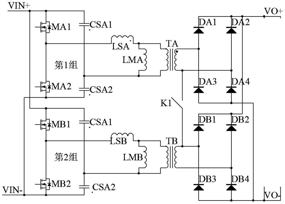
[0004] In order to meet the requirements of wide output voltage range and constant power, the DC-DC converter topology used is basically through electronic switches (relays, semiconductor switching tubes, etc.) and logic control circuits, through different combinations of switches to achieve wide output voltage The range includes changing the series-parallel connection of the primary or secondary windings of multi-winding transformers through switch switching, changing the series-parallel connection of multiple outputs through switch switching, and using the principle of diode voltage doubler rectification to achieve a wide range of output voltages through switch switching; these Although the technology can achieve constant power and wide-range voltage output, it increases additional costs and increases the size of the equipment. For example, by switching the turn ratio of the transformer, the transformer often involves complex windings and is large in size. In addition, the switching is complicated and the switching time It needs to be shut down for a long time to realize the switching, and the overload protection of the parallel section and the series section also need to consider the stress of these devices, switching overvoltage surge suppression, especially when the power demand is greater, this kind of problem is more prominent and seriously affects actual use

Method used


Image

  • Half-bridge LLC constant-power wide-range converter topology and circuit
  • Half-bridge LLC constant-power wide-range converter topology and circuit
  • Half-bridge LLC constant-power wide-range converter topology and circuit

Examples


specific Embodiment 1

[0042] A half-bridge LLC constant power wide range converter topology of the present application, such as figure 1 As shown, it includes a switch unit, a half-bridge LLC converter unit I, and the half-bridge LLC converter unit I includes two half-bridge LLC converters with the same structure, and the transformer primary in the half-bridge LLC converter is connected to the half-bridge LLC unit , the secondary is connected to the full-bridge rectifier circuit; the opposite end of the secondary winding of the first transformer TA in the first half-bridge LLC converter is connected to one end of the switch unit K1, and the other end of the switch unit K1 is connected to the second half-bridge LLC converter The secondary terminal with the same name of the secondary winding of the second transformer TB; the first half-bridge LLC unit is connected in parallel with the second half-bridge LLC unit.

[0043] The first half-bridge LLC unit in the first half-bridge LLC converter includes ...

specific Embodiment 2

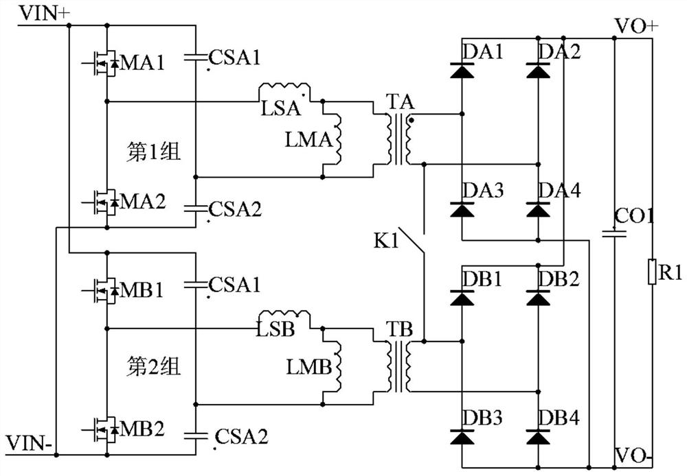
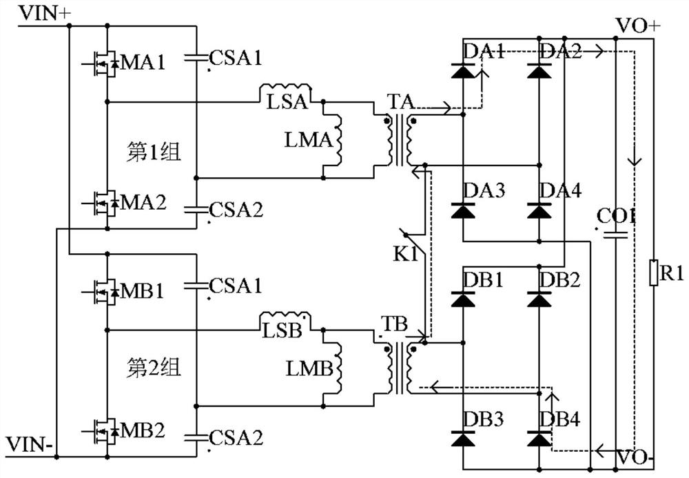
[0052] A half-bridge LLC constant power wide range converter circuit of the present application, such as figure 2 As shown, it includes a filter circuit and the topology of the half-bridge LLC constant power wide-range converter described in Embodiment 1. The filter circuit is connected to the output of the half-bridge LLC constant power wide-range converter topology. The filter circuit includes a filter capacitor CO1 connected to The resistor R1 between the two output ends of the half-bridge LLC constant power wide range converter topology serves as the total load of the half bridge LLC constant power wide range converter circuit.

[0053] A half-bridge LLC constant power wide range converter circuit of the present application has the following working principle: when the control switch K1 is turned off, the secondary output rectification part of the transformer works in parallel mode, so as to meet the demand for low voltage and high current output; When the control switch ...

specific Embodiment 3

[0067] A half-bridge LLC constant power wide range converter topology of the present application, such as Figure 7 As shown, it includes two half-bridge LLC converter units II and two switch units, and the two half-bridge LLC converter units II have the same structure.

[0068] The first half-bridge LLC converter unit II includes two half-bridge LLC converters A / B with the same structure, the primary of the transformer TA in the half-bridge LLC converter A is connected to the half-bridge LLC unit, and the secondary is connected to the first full-bridge rectifier circuit .

[0069] The half-bridge LLC unit A in the half-bridge LLC converter A / B is connected in series with the half-bridge LLC unit B in the half-bridge LLC converter B, and the series point M1 serves as the first level balance point. The series connection of the A half-bridge LLC unit and the B half-bridge LLC unit serves as a series combination of the first half-bridge LLC unit of the first half-bridge LLC conv...


PUM


Abstract

The invention discloses a half-bridge LLC constant-power wide-range converter topology and circuit, which comprises a switch unit and a half-bridge LLC converter unit, the output of a full-bridge rectifier circuit of the half-bridge LLC converter unit is connected with a filter circuit, primary LLC half-bridge converters of two converter transformers are connected in parallel or in series, and the primary LLC half-bridge converters are connected in parallel or in series. Secondary sides of two adjacent transformers are connected together through a controllable switch, and when the control switch is switched off, output rectification parts of the secondary sides of the transformers work in a parallel mode, so that the requirement of low-voltage large-current output is met; when the control switch is closed, the secondary output rectification part of the transformer works in a series mode, so that the requirement of high-voltage output is met, and the purpose of wide output voltage is achieved.

Description

technical field [0001] The invention relates to the technical field of power electronics, in particular to a half-bridge LLC constant power wide range converter topology and circuit. Background technique [0002] DC-DC converter is an important electrical equipment to realize the conversion and transmission of electrical energy in electrical systems. It is widely used in the fields of power electronics technology, communication power supply, LED lighting power supply and some experimental power supplies. The DC-DC converter can convert the input DC to another fixed or adjustable DC, including DC-DC direct conversion and DC-AC-DC indirect conversion; direct conversion is generally direct conversion without transformer isolation, The indirect conversion adds an AC link in the middle of the converter, and usually uses a transformer to isolate the input and output, so it is also called a DC isolation converter. [0003] In various fields, DC-DC converters are required to have a...

Claims


Application Information

Patent Timeline
IPC IPC(8): H02M3/335H02M1/15
CPCH02M3/3353H02M1/15
Inventor 张乐乐汪晓霞王旭吕玮
Owner BEIJING DYNAMIC POWER CO LTD
Learn More