

Constant current DC (Direct Current)-DC converter utilizing digital PWM (Pulse-Width Modulation) control and constant current LED (Light Emitting Diode) drive DC-DC converter
A DC-DC and converter technology, applied in the field of constant current DC-DC converters and constant current LED drive DC-DC converters, can solve complex control algorithms and circuits, high chip cost, high operating frequency and other problems, to achieve the effect of simple circuit structure, good constant current effect, and small chip area
- Summary
- Abstract
- Description
- Claims
- Application Information
AI Technical Summary
Problems solved by technology
Method used
Image

Examples
Embodiment Construction
[0032] The preferred embodiments of the present invention will be described below in conjunction with the accompanying drawings. It should be understood that the preferred embodiments described here are only used to illustrate and explain the present invention, and are not intended to limit the present invention.
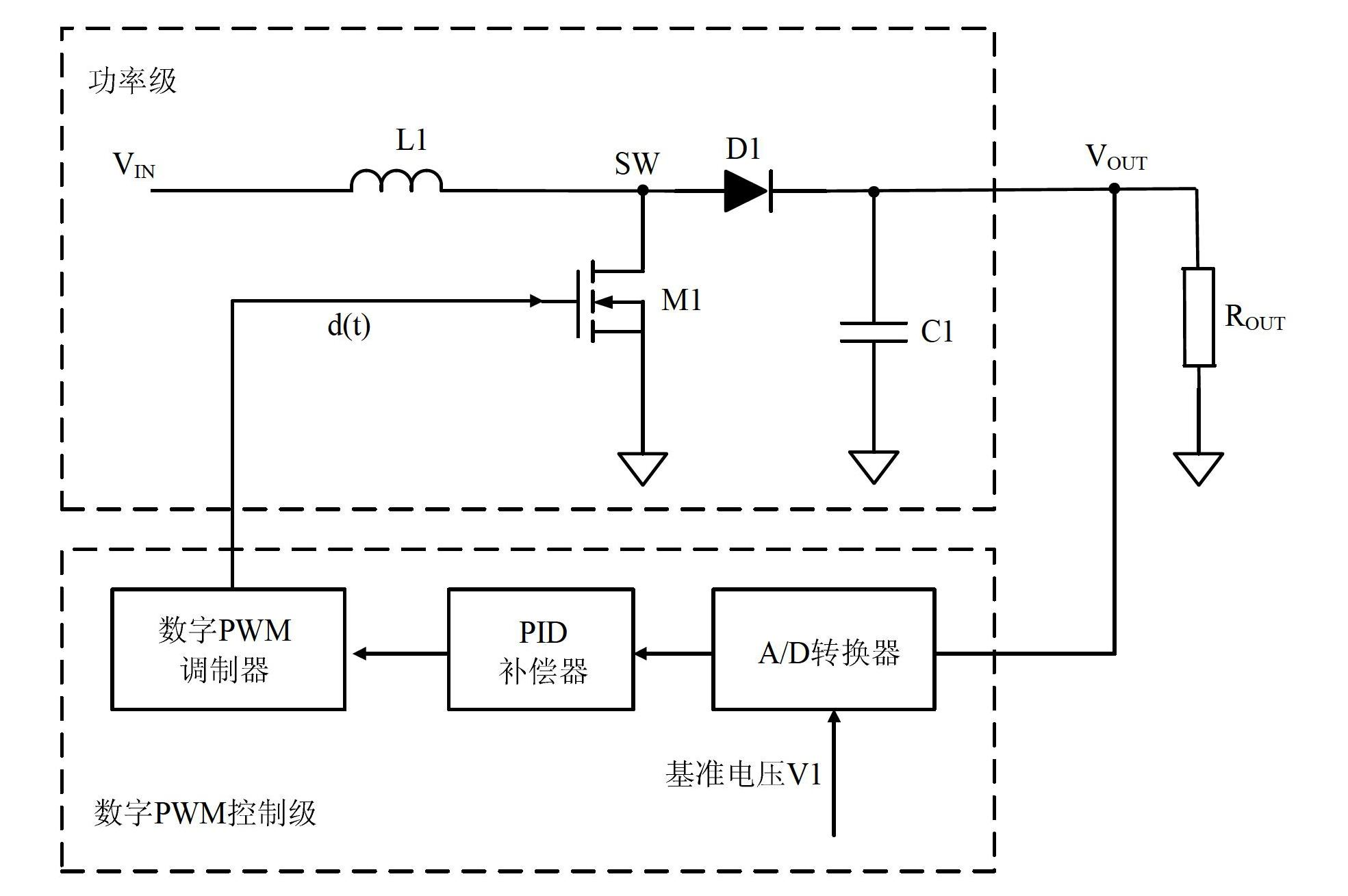
[0033] Embodiment of DC-DC Converter Using Digital PWM Control
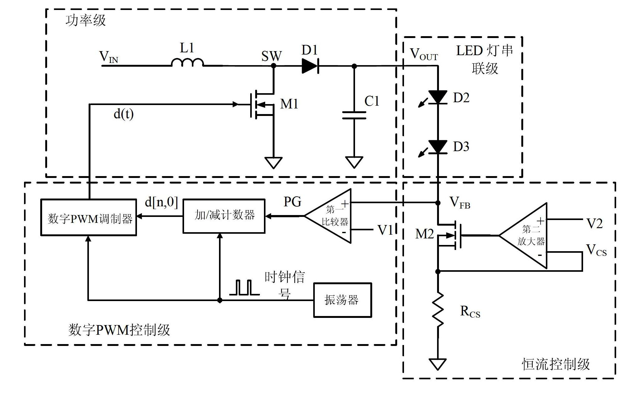
[0034] According to an embodiment of the present invention, a constant current DC-DC converter adopting digital PWM control is provided. Such as figure 2 As shown, the power stage and the digital PWM control stage electrically connected in this embodiment, the constant current control stage electrically connected with the power stage and the digital PWM control stage respectively, and the constant current control stage electrically connected between the power stage and the constant current control stage LED lights in series.
[0035]Wherein, the above-mentioned digital PWM control stage includes a...
PUM
 Abstract
Description
Claims
Application Information