Method of controlling flashing time of external flash lamp

A flash time and flash technology, applied in the flash field, can solve problems such as the inability to improve the photo quality and the inability to find the best flash timing for the xenon flash.

Inactive Publication Date: 2017-01-04
PAN JIT INT
View PDF6 Cites 8 Cited by
  • Summary
  • Abstract
  • Description
  • Claims
  • Application Information

AI Technical Summary

Problems solved by technology

[0006] However, due to the limitation of the cycle shutter, the external xenon flash often cannot find the best flash timing, resulting in the failure to improve the photo quality

Method used


Image

  • Method of controlling flashing time of external flash lamp
  • Method of controlling flashing time of external flash lamp
  • Method of controlling flashing time of external flash lamp

Examples


Embodiment Construction

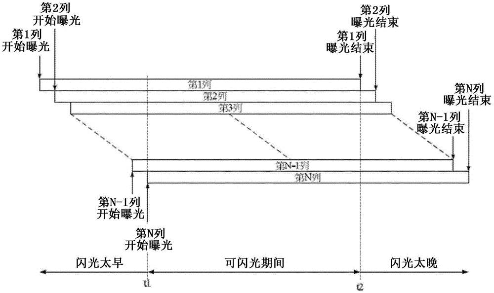
[0044] figure 2A schematic diagram of suitable flash times according to an embodiment of the present invention is shown. Please refer to figure 2 , the suitable flash time is only between t1 and t2. The flash within this period can be received by the photosensitive elements of each row, that is to say, the flashable time is the overlapping area of ​​the exposure time of all photosensitive elements. If the flash time is earlier than t1, the photosensitive elements in the rear row will not be exposed to light, and if the flash time is later than t2, the photosensitive elements in the front row will not be exposed to light. However, since the mobile device usually performs multi-tasking operation, the delay time from when the user presses the shutter command to t1 or t2 is not fixed. Therefore, there is no feasible and reliable method in the prior art to ensure that the flash time of the external flash can be stably controlled between t1 and t2, so that the use of the extern...


PUM


Abstract

The invention provides a method of controlling flashing time of an external flash lamp. The method comprises steps of detecting a specific event, wherein the occurrence time of the specific event has a fixed time span relative to the exposure starting time of a first row of photosensitive elements; determining whether a single flashing period exists or not, wherein flashes in the period can be received by each row of photosensitive elements; when the single flashing period exists, carrying out single flashing after a delayed period after occurrence of the specific event; and when the single flashing period does not exist, carrying out first flashing after a delayed period after occurrence of the specific event, and carrying out second flashing after a period after the first flashing.

Description

technical field [0001] The present invention relates to a flashlight technology, and more specifically, the present invention relates to a photographing method for an external flashlight of a mobile device. Background technique [0002] Due to the improvement of the pixel and quality of digital photography, it has become a trend to equip mobile devices (such as mobile phones, tablet computers) with camera functions. However, these built-in digital cameras have not been able to match the performance of traditional digital cameras in low light or backlit environments. [0003] Although some built-in digital cameras are also equipped with LED (light-emitting diode) fill lights, the amount of fill light of LED fill lights is severely limited due to battery capacity and LED heat dissipation of mobile devices. When the distance of the object to be illuminated exceeds one meter, the LED cannot provide enough light source to properly expose the photosensitive element. [0004] Xen...

Claims


Application Information

Patent Timeline
Patent Type & Authority Applications(China)
IPC IPC(8): H04N5/235H04N5/232
Inventor 谢孟諴
Owner PAN JIT INT
Why Eureka
Try Eureka