
Mechanical device and control method

A mechanical device, detection and control technology, applied in the field of robotics, can solve problems such as damage to internal components

Inactive Publication Date: 2017-01-11
LENOVO (BEIJING) CO LTD
View PDF6 Cites 0 Cited by
  • Summary
  • Abstract
  • Description
  • Claims
  • Application Information

AI Technical Summary

Problems solved by technology

[0006] The embodiment of the present application provides a mechanical device and a control method to solve the technical problem that the internal components of the mechanical device are easily damaged when there is an unexpected external force intervention in the prior art, and realizes the technology of protecting the internal components of the mechanical device Effect

Method used


Image

  • Mechanical device and control method
  • Mechanical device and control method
  • Mechanical device and control method

Examples


Embodiment 1

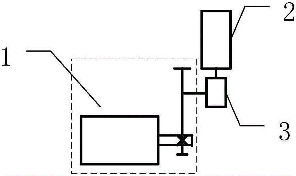
[0058] Please refer to figure 1 , is a structural schematic diagram of a mechanical device provided in Embodiment 1 of the present application, including: a driving part 1, a driven part 2, an elastic part 3, and the elastic part 3 is arranged between the driving part 1 and the driven part 2, and is driven When the current relative position of the component 2 and the driving component 1 changes from the first relative position to the second relative position, the driving component 1 is adjusted from the normal driving state to the emergency driving state and moves in the first direction.

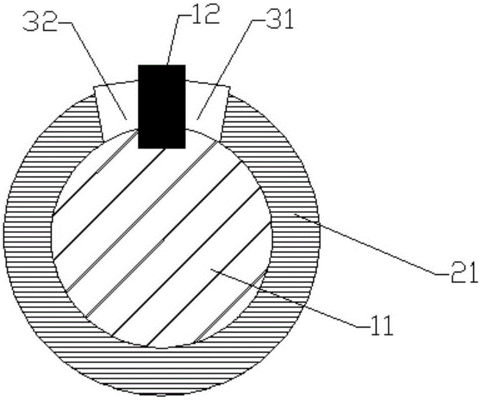
[0059] In the specific implementation process, those skilled in the art can form a rotary motion pair through a clearance fit between the driven part 2 and the driving part 1 according to actual needs, and can also form a linear motion through a clearance fit between the driven part 2 and the driving part 1 As a pair, the driving part 1 and the driven part 2 can also be assembled into a bear...

Embodiment 2

[0077] Based on the same inventive concept as the first embodiment of the present application, the second embodiment of the present application provides a control method applied to a mechanical device, the method comprising:

[0078] When the current relative position of the driven part and the driving part in the mechanical device changes from the first relative position to the second relative position, the driving part is adjusted from the non-driving part to the driving state and moves in the first direction .

[0079] Specifically, when the driving part is in the normal driving state, there is an unexpected external force intervening in the mechanical device, such as artificially moving the driven part or the driving part, so that the relative position between the driving part and the driven part in the mechanical device changes from the initial When the first relative position is changed to the second relative position, the driving part will be adjusted from the normal dr...


PUM


Abstract

The invention discloses a mechanical device and a control device. The mechanical device comprises a driving part, a driven part and an elastic part which is arranged between the driving part and the driven part, wherein when current relative positions of the driven part and the driving part are transformed from first relative positions into second relative positions, the driving part is adjusted from a normal driving state to an emergent driving state and moves toward a first direction.

Description

technical field [0001] The invention relates to the field of robots, in particular to a mechanical device and a control method. Background technique [0002] With the continuous development of robot technology, more and more service robots will enter the home, bringing more convenience to people's life. [0003] In the prior art, the mechanical design of service robots mainly adopts rigid design methods, for example, using motors, reducers, etc. The advantages of this rigid connection are mainly simple structural assembly, precise motor control and fast operation response, and the ability to meet the basic task requirements of operation and application. [0004] However, in the process of realizing the technical solution of the invention in the embodiment of the present application, the inventor of the present application found that the above-mentioned technology has at least the following technical problems: [0005] Since the drive unit in the prior art is mainly rigidly...

Claims


Application Information

Patent Timeline
Patent Type & Authority Applications(China)
IPC IPC(8): B25J9/10B25J19/02
Inventor 宁柯军
Owner LENOVO (BEIJING) CO LTD
Learn More