
Color film substrate and manufacturing method thereof, display panel and manufacturing method thereof, and display device

A technology for a color filter substrate and a manufacturing method, applied in the field of display equipment, can solve problems such as damage to a fingerprint identification module, and achieve the effects of improving production efficiency, reducing production costs, and shortening process flow

Active Publication Date: 2020-11-20
BOE TECH GRP CO LTD
View PDF8 Cites 0 Cited by
  • Summary
  • Abstract
  • Description
  • Claims
  • Application Information

AI Technical Summary

Problems solved by technology

[0004] In view of the shortcomings of the existing methods, the present application proposes a color film substrate and its manufacturing method, a display panel and its manufacturing method, and a display device to solve the problem of fingerprint identification in the polarization processing process of the fingerprint identification module in the display panel in the prior art. The technical problem that the module is easily damaged

Method used


Image

  • Color film substrate and manufacturing method thereof, display panel and manufacturing method thereof, and display device
  • Color film substrate and manufacturing method thereof, display panel and manufacturing method thereof, and display device
  • Color film substrate and manufacturing method thereof, display panel and manufacturing method thereof, and display device

Examples


Embodiment Construction

[0048] The present application is described in detail below, and examples of embodiments of the present application are shown in the drawings, wherein the same or similar reference numerals denote the same or similar components or components having the same or similar functions throughout. Also, detailed descriptions of known technologies will be omitted if they are not necessary to illustrate the features of the present application. The embodiments described below by referring to the figures are exemplary only for explaining the present application, and are not construed as limiting the present application.

[0049] Those skilled in the art can understand that, unless otherwise defined, all terms (including technical terms and scientific terms) used herein have the same meanings as commonly understood by those of ordinary skill in the art to which this application belongs. It should also be understood that terms, such as those defined in commonly used dictionaries, should be ...


PUM

PropertyMeasurementUnit
thicknessaaaaaaaaaa
thicknessaaaaaaaaaa

Abstract

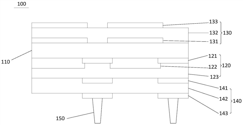
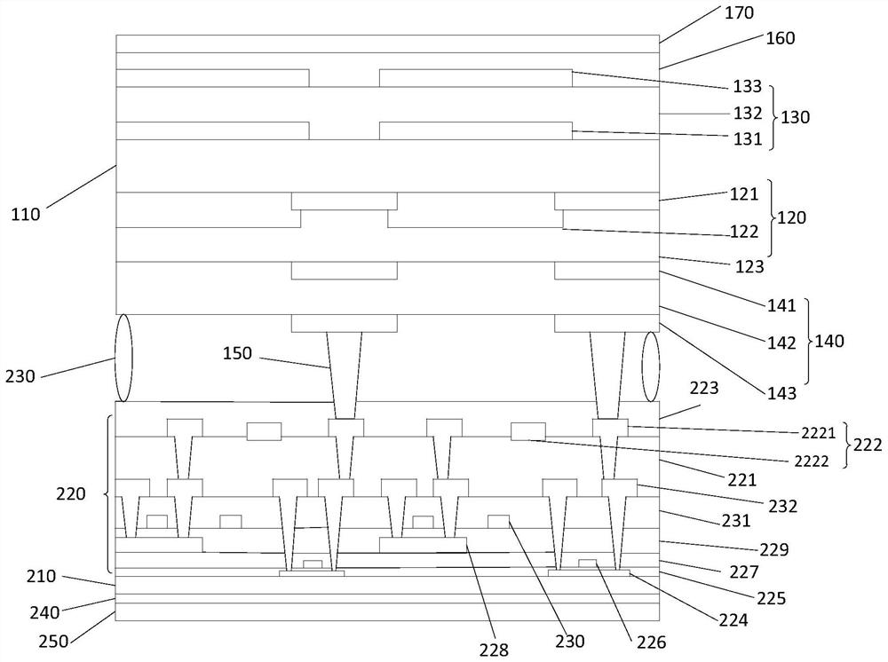
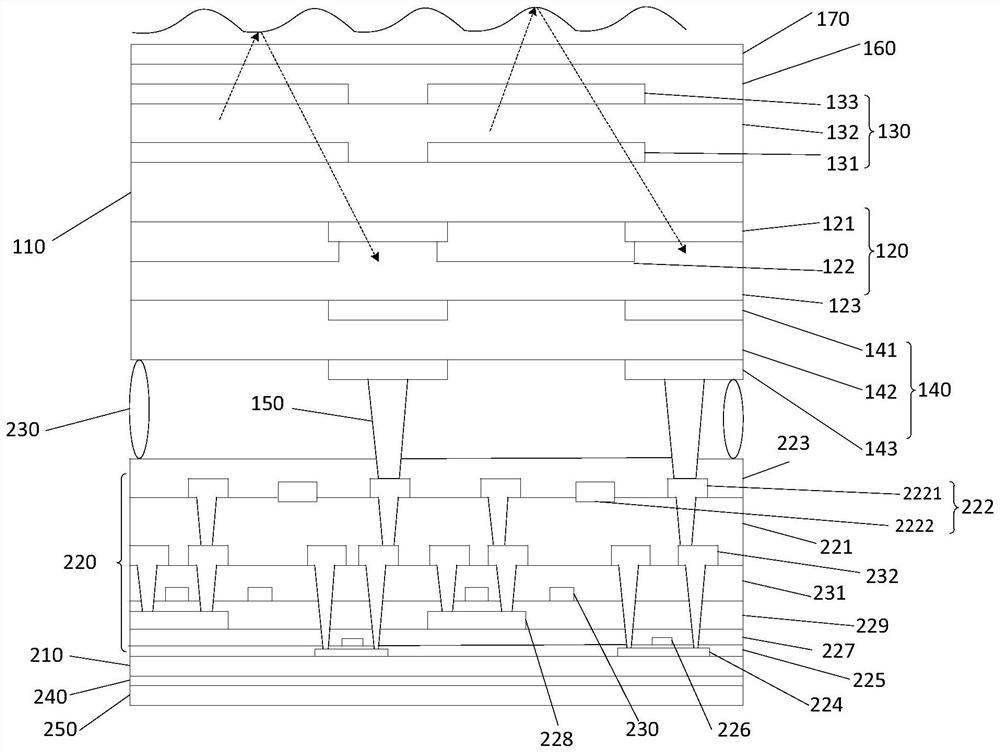
The embodiment of the invention provides a color film substrate and a manufacturing method thereof, a display panel and a manufacturing method thereof, and a display device. The color film substrate comprises a transparent substrate and a photoresist layer which are laminated; a first piezoelectric structure, arranged on one side, far away from the photoresist layer, of the transparent substrate and used for sending an ultrasonic signal according to the driving electric signal; a second piezoelectric structure, arranged on the side, away from the transparent substrate, of the photoresist layerand used for receiving a reflected ultrasonic signal formed after the ultrasonic signal is reflected and converting the reflected ultrasonic signal into a fingerprint recognition electric signal; a conductive support column, arranged on one side, far away from the photoresist layer, of the second piezoelectric structure, one end of the conductive support column being electrically connected with the second piezoelectric structure, and the other end of the conductive support column being electrically connected with a first electrode structure of a thin film transistor structure of the array substrate to transmit fingerprint identification electric signals. The first piezoelectric structure and the second piezoelectric structure which are used for fingerprint identification are arranged in the color film substrate, so that damage to wiring in the polarization process is avoided, and meanwhile, the production efficiency is improved.

Description

technical field [0001] The present application relates to the technical field of display devices. Specifically, the present application relates to a color filter substrate and a manufacturing method, a display panel and a manufacturing method, and a display device. Background technique [0002] With the development of display technology and mobile communication technology, mobile electronic devices such as smart phones and tablet computers have become indispensable tools in people's lives, especially smart phones often store users' personal information. In order to improve the security of mobile electronic devices represented by smart phones, the existing mobile electronic devices mostly adopt the identity authentication method of fingerprint recognition, which not only protects the user's personal information but also facilitates the use of the user. [0003] The existing mobile electronic devices with fingerprint recognition function are mainly under-display fingerprint re...

Claims


Application Information

Patent Timeline
Patent Type & Authority Applications(China)
IPC IPC(8): G02F1/1333G02F1/1335G02F1/1339G06K9/00
CPCG02F1/13338G02F1/133514G02F1/133516G02F1/13394G06V40/1306
Inventor 崔钊张锋刘文渠吕志军宋晓欣孟德天王利波董立文侯东飞姚琪黄海涛
Owner BOE TECH GRP CO LTD
Learn More