
Movable pickup mechanism
A technology of driving shaft and vertical plate, applied in the field of mobile pick-up mechanism, can solve the problems of poor use effect, difficult control, slow action process, etc., and achieve the effect of increasing flexibility and adaptability, avoiding sluggishness, and improving efficiency
- Summary
- Abstract
- Description
- Claims
- Application Information
AI Technical Summary
Problems solved by technology
Method used
Image

Examples
Embodiment Construction
[0009] The present invention will be described in further detail below through specific implementation examples and in conjunction with the accompanying drawings.
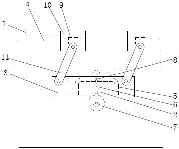
[0010] figure 1 It shows the mobile pick-up mechanism provided by the present invention, including a vertical plate 1, a vertical swing bar 2 located at the back of the vertical plate 1, a jaw mounting plate 3 located at the front of the vertical plate 1, and a horizontal horizontal plate fixed on the upper front of the vertical plate 1 A slide rail 4; a chute 5 is provided on the surface of the vertical plate 1, and the chute 5 is in an inverted U shape; the upper part of the swing rod 2 is provided with a vertical strip hole 6, and the lower end is connected with a motor 7 to drive it to swing; A sliding pin 8 is provided in the strip hole 6, and one end of the sliding pin 8 passes through the chute 5 and is connected with the jaw mounting plate 3; the horizontal slide rail 4 is located above the chute 5, and the...
PUM
 Abstract
Description
Claims
Application Information