
Installation device and method for swinging and moving long slings of girder sections on bank slopes of suspension bridges

An installation device and technology for suspension bridges, applied in bridges, bridge construction, erection/assembly of bridges, etc., can solve the problems of prolonged construction time, poor economic effect, poor stability, etc., and achieve the goal of reducing construction facilities, reducing construction costs, and preventing risks. Effect

Active Publication Date: 2019-06-25
CHINA FIRST HIGHWAY ENG CO LTD
View PDF4 Cites 0 Cited by
  • Summary
  • Abstract
  • Description
  • Claims
  • Application Information

AI Technical Summary

Problems solved by technology

Due to the limitation of operating conditions, the spanning crane can only carry out vertical or small-scale construction
[0004] For cross-river bridges, it is more feasible and economical to transport the stiffening girders on the shore by water. Since barges cannot reach below the installation position of the girder section, the vertical or small range of the spanning cable crane cannot meet the construction needs. In this case, In order to smoothly move the stiffening beam from the transport ship to the shore, the existing technology is to set up supports on the bank slope or set up supports with different heights. Hoist the stiffened beams to the shore, and transport the stiffened beams to the predetermined installation location by the shore transportation facilities; for the location with large height difference, erect the beam transportation bracket, which has poor stability and poses a safety hazard to the swinging construction, and needs to be used A large amount of steel has poor economic effect, and it takes a long time to erect before construction, prolonging the construction time

Method used


Image

  • Installation device and method for swinging and moving long slings of girder sections on bank slopes of suspension bridges
  • Installation device and method for swinging and moving long slings of girder sections on bank slopes of suspension bridges
  • Installation device and method for swinging and moving long slings of girder sections on bank slopes of suspension bridges

Examples


Embodiment Construction

[0047] The technical solutions of the present invention will be clearly and completely described below in conjunction with the accompanying drawings. Apparently, the described embodiments are some of the embodiments of the present invention, but not all of them. Based on the embodiments of the present invention, all other embodiments obtained by persons of ordinary skill in the art without making creative efforts belong to the protection scope of the present invention.

[0048] In the description of the present invention, it should be noted that the terms "center", "upper", "lower", "left", "right", "vertical", "horizontal", "inner", "outer" etc. The indicated orientation or positional relationship is based on the orientation or positional relationship shown in the drawings, and is only for the convenience of describing the present invention and simplifying the description, rather than indicating or implying that the referred device or element must have a specific orientation, ...


PUM


Abstract

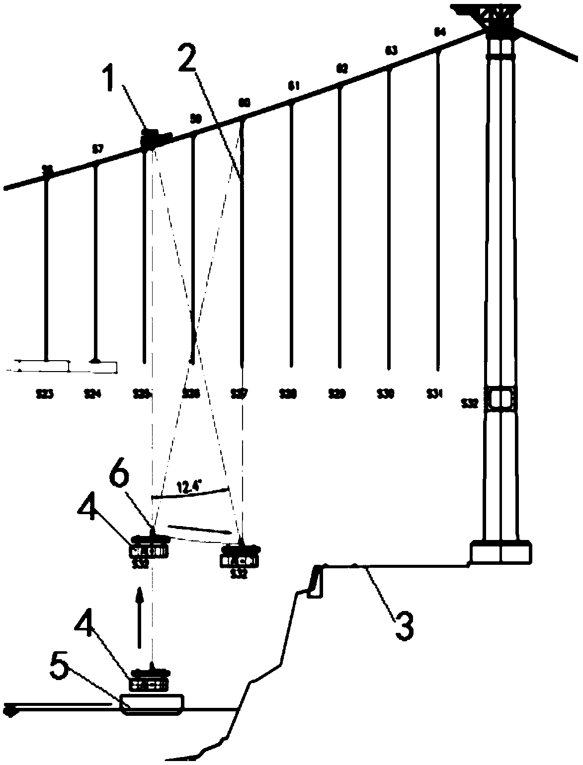
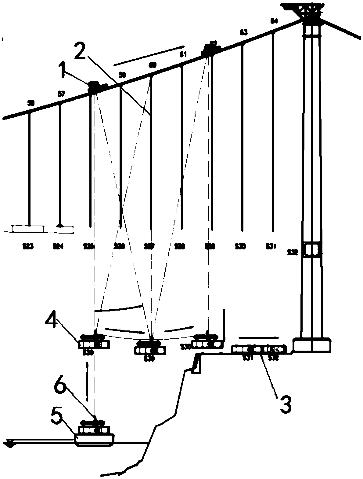
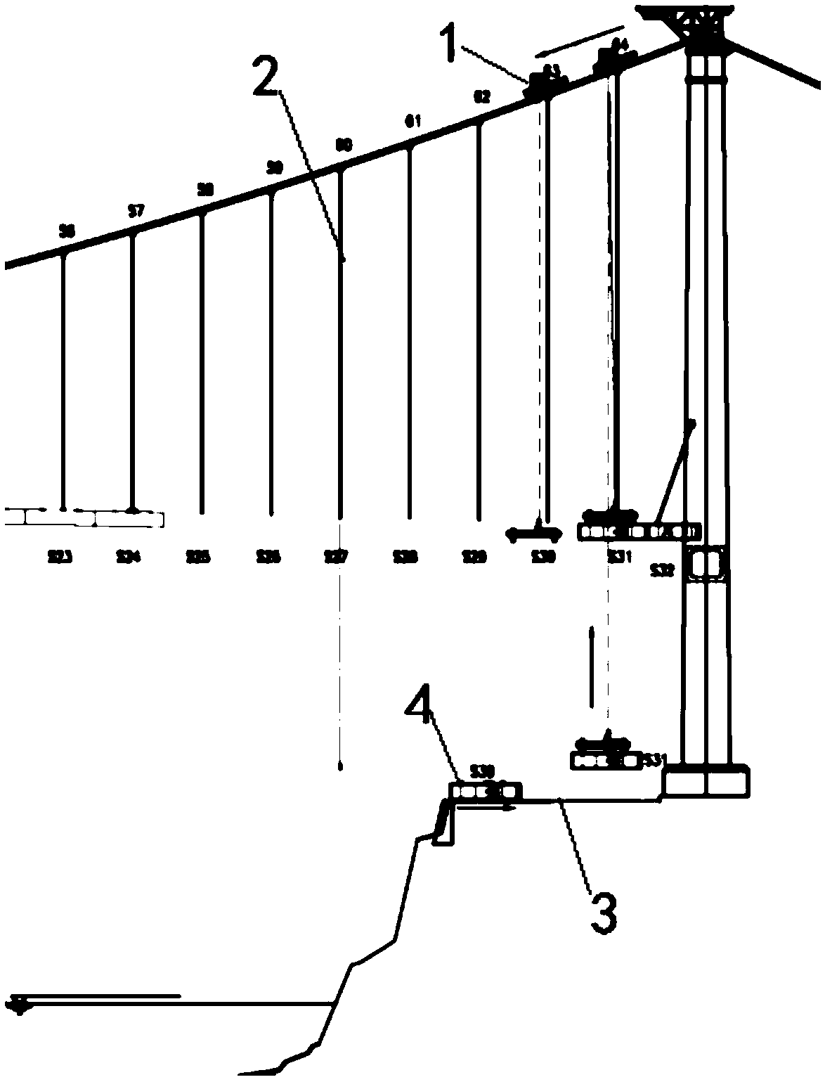
The invention discloses a suspension bridge bank slope beam section long sling swing-shifting mounting device and method, and relates to the field of bridge construction devices. The device comprises a cable crane, at least one first sling and a transportation system. The cable crane is utilized for vertically lifting a stiffening beam from a barge to a swing-shifting position, the first slings are dragged to be connected with a lifting device for swing shifting, all the load of the stiffening beam is transferred to the first slings to eliminate connection of the cable crane and the lifting device, the cable crane moves to the lifting position and locates and is connected with the lifting device along the position opposite to the first slings, swing shifting is carried out again, the stiffening beam swing-shifts to the transportation system on a bank, and the stiffening beam is dragged to a mounting preparation position through traction equipment. Under the conditions that the bank terrain is steep, construction facility mounting difficulty is large, and the distance between a main tower and the water line is large, the swing-shifting mounting device and method are used, risks can be prevented, construction facilities on the construction bank can be greatly reduced, the construction cost can be reduced, and construction preparation time can be shortened.

Description

technical field [0001] The invention relates to the field of bridge construction devices, in particular to a device and method for swinging and installing long suspension cables on bank slope beam sections of suspension bridges. Background technique [0002] The construction method of the suspension bridge was invented in the early 19th century, and many bridges use this construction method. Modern suspension bridges are evolved from cable bridges, and are mainly applicable to long-span and extra-long-span highway bridges. Today's long-span bridges all use this structure, which is the main form of long-span bridges. [0003] The deck of modern suspension bridges is composed of steel box stiffening girders. Since suspension bridges are mainly long-span bridges, the volume and weight of the stiffening girders are generally large. In the construction of the stiffened girder of the suspension bridge, the girder section is transported to the bridge position by water, and install...

Claims


Application Information

Patent Timeline
Patent Type & Authority Patents(China)
IPC IPC(8): E01D21/00
CPCE01D21/00
Inventor 张志新任威李文李鸿盛宾熊毛超军郭永兵
Owner CHINA FIRST HIGHWAY ENG CO LTD
Learn More