
Steel-concrete combined structure conical cast iron bolt connecting piece

A technology of concrete and connectors, which is applied to bridge parts, bridge materials, bridges, etc., can solve the problems of performance impact of bolt shear parts, large wet operation, and low initial stiffness of bolt connectors, so as to reduce time and cost, reduce Quantity, effect of increasing bearing capacity

Active Publication Date: 2019-10-22
ZHEJIANG UNIV
View PDF11 Cites 3 Cited by
  • Summary
  • Abstract
  • Description
  • Claims
  • Application Information

AI Technical Summary

Problems solved by technology

[0003] Scholars at home and abroad have studied the performance and advantages of bolted joints from different angles and directions, but the bolted joints in the existing research often cannot realize partial replacement of shear joints without replacing the concrete slab
In addition, the existing bolted joints often need to post-cast the concrete around the bolts. The wet work on site is relatively large and the performance of the bolted shear members is affected by the quality of the post-cast concrete.
On the other hand, since the bolted joint generally needs to reserve holes on the steel beam, and often due to processing and installation errors, the joint has a certain gap in the reserved hole of the steel beam, making the initial stiffness of the bolted joint low.

Method used


Image

  • Steel-concrete combined structure conical cast iron bolt connecting piece
  • Steel-concrete combined structure conical cast iron bolt connecting piece
  • Steel-concrete combined structure conical cast iron bolt connecting piece

Examples


Embodiment

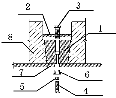
[0025] In order to explore the mechanical properties of TIBC, referring to the European EC-4 specification, a set of push-out test pieces was made, and the overall size of the test pieces was rolled out. The nominal diameter of the lower high-strength bolts of the test piece is 12 mm, and they are 8.8-grade high-strength bolts. The steel beams for the test pieces are all made of Q235 hot-rolled H-shaped steel with a specification of HM 250×250×9×14. The flanges of the steel beams need to have holes matching the size of the lower high-strength bolts. The concrete used for the specimens is the same batch of concrete, the concrete strength is C45, and the concrete is equipped with two-way HPB235 grade stirrups.

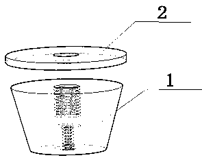
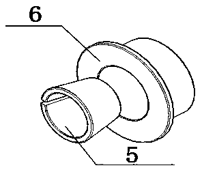
[0026] The inner and outer taper sleeves fixed by bolts are all made of 45# steel, and their dimensions must correspond to those of the lower high-strength bolts. The conical cast iron block is a conical cast iron block with a certain taper on the outside. The cast iron...


PUM

PropertyMeasurementUnit
diameteraaaaaaaaaa
diameteraaaaaaaaaa
diameteraaaaaaaaaa

Abstract

The invention discloses a steel-concrete combined structure conical cast iron bolt connecting piece. The piece comprises a conical cast iron block, a conical hole cover plate, an upper fixing bolt, alower high-strength bolt, a bolt fixing inner taper sleeve and a bolt fixing outer taper sleeve, wherein the conical cast iron block is a circular truncated cone-shaped cast iron block with the taperand is placed in a concrete preformed hole with the corresponding taper, and the taper of the preformed hole enables the conical cast iron block not to be pushed downwards; the conical hole cover plate is fixed on the conical cast iron block through the upper fixing bolt, a hole is reserved in a lower steel beam, the lower high-strength bolt, the bolt fixing inner taper sleeve and the bolt fixingouter taper sleeve penetrate through the reserved hole of the steel beam, so that the steel beam is connected with the conical cast iron block and then is connected with concrete. The piece has relatively good initial rigidity. The conical cast iron block can increase the compressive area of the concrete, so that control by the compressive strength of the concrete is relieved, the bearing capacityof a single shear connecting piece can be increased, so that the shear connecting pieces with larger diameters are used, and the number of the shear connecting pieces is reduced.

Description

technical field [0001] The invention relates to a novel steel-concrete composite structure shear connector in the field of civil engineering, in particular to a detachable steel-concrete composite structure tapered cast iron bolt connector. Background technique [0002] In recent years, steel-concrete composite bridges have been widely used in the world. Bridges using this structure have the advantages of high rigidity, small superstructure height and high ductility. Among various steel-concrete shear connectors, welded stud connectors have become the most practical shear connectors to realize the composite effect of steel beams and concrete slabs because of their fast welding speed, excellent mechanical properties, and extensive comprehensive research results. From the perspective of sustainable development, the disassembly and recyclability of the building is very important, and the composite beam concrete slabs using traditional welded head stud shear connections cannot b...

Claims


Application Information

Patent Timeline
Patent Type & Authority Applications(China)
IPC IPC(8): E01D19/00E01D101/24E01D101/30
CPCE01D19/00E01D2101/24E01D2101/30
Inventor 陈驹严鑫
Owner ZHEJIANG UNIV
Learn More