Automatic regulating tangential hydraulic generator with quick start-up function

A hydro-generator and automatic adjustment technology, applied in the direction of impact engine, hydroelectric power generation, engine control, etc., can solve the problems of long time consumption, reduced flexibility, lack of water flow adjustment mechanism in the nozzle, etc., to change the power generation, The effect of satisfying flexibility

Active Publication Date: 2017-01-11
ZHEJIANG LINGBEN MACHINERY & ELECTRONICS
View PDF5 Cites 6 Cited by
  • Summary
  • Abstract
  • Description
  • Claims
  • Application Information

AI Technical Summary

Problems solved by technology

[0003] At the beginning of the operation of the existing hydroelectric generator, the rotation of the blades causes the angle between the blades and the water flow velocity to change continuously. During the angle change process, the work done by the water flow on a single blade per unit time first gradually increases to a certain value, and then It gradually decreases again. When it decreases to a certain range, the water flow will do work on the next blade, and the speed-up process of the turbine will be realized by doing work on multiple blades in turn. As a result, it takes a long time for the turbine to accelerate to the rated speed. At the same time, when the turbine generator is connected to the grid, the load in the grid system is in a process of constant change, and the nozzle in the turbine generator lacks a corresponding water flow adjustment mechanism. As a result, the power generation of the turbine is fixed, resulting in reduced flexibility

Method used


Image

  • Automatic regulating tangential hydraulic generator with quick start-up function
  • Automatic regulating tangential hydraulic generator with quick start-up function
  • Automatic regulating tangential hydraulic generator with quick start-up function

Examples


Embodiment Construction

[0027] The present invention is described in further detail now in conjunction with accompanying drawing. These drawings are all simplified schematic diagrams, which only illustrate the basic structure of the present invention in a schematic manner, so they only show the configurations related to the present invention.

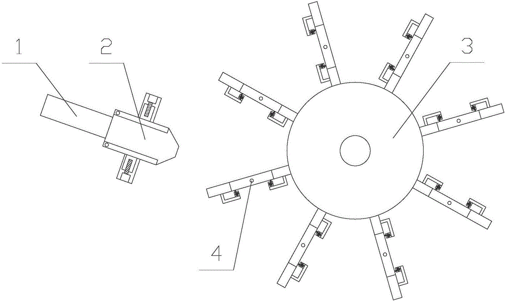
[0028] Such as Figure 1-Figure 7 As shown, a quick-start self-adjusting cut-off hydroelectric generator includes a drive unit and a power generation unit, the drive unit is connected to the power generation unit, and the power generation unit includes a wheel disc 3 and several blades 4, the The blades 4 are evenly distributed on the outer side of the wheel disk 3 along the circumference of the center of the wheel disk 3. The drive unit includes a water inlet pipe 1 and a nozzle 2. The water inlet pipe 1 communicates with the nozzle 2, and the water outlet of the nozzle 2 is close to the blades. 4;

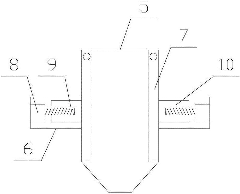
[0029] The nozzle 2 includes a casing 5 and regulating pi...


PUM


Abstract

The invention relates to an automatic regulating tangential hydraulic generator with a quick start-up function. The hydraulic generator comprises a driving unit and an electricity generating unit which are in transmission connection with each other, wherein the electricity generating unit comprises a wheel disc and a plurality of blades; the blades are circumferentially and uniformly distributed on the outer side of the wheel disc along the circle center of the wheel disc; and the driving unit comprises a water inlet pipe and a nozzle which communicate with each other. According to the automatic regulating tangential hydraulic generator, sliding rods are driven by second driving motors in angle adjusting mechanisms to move, so that impact blades can rotate along rotating shafts; accordingly, the direction of water flowing from the nozzle as well as the included angles among the impact blades can be adjusted, the water flow can be sufficiently utilized for applying work, and the hydraulic generator can be quickly started up and reach the rated rotating speed; not only that, sleeves can be moved by rotating first driving motors in adjusting pipes, so that the include angle between every two side plates can be controlled and the water flow rate can be adjusted; and accordingly, the electricity generating power of the hydraulic generator can be changed and the flexibility requirement of the hydraulic generator can be met.

Description

technical field [0001] The invention relates to a fast-starting self-adjusting cut-off hydraulic generator. Background technique [0002] The cutting-type hydro-generator is a water turbine that uses the kinetic energy of high-pressure jet water to do work. The water in the high-head reservoir passes through the pressure pipe, and the high-pressure water passes through the nozzle of the water turbine to become a high-speed jet of water, which rushes to the blades of the water turbine to make the water turbine rotate to do work. [0003] At the beginning of the operation of the existing hydroelectric generator, the rotation of the blades causes the angle between the blades and the water flow velocity to change continuously. During the angle change process, the work done by the water flow on a single blade per unit time first gradually increases to a certain value, and then It gradually decreases again. When it decreases to a certain range, the water flow will do work on the n...

Claims


Application Information

Patent Timeline
Patent Type & Authority Applications(China)
IPC IPC(8): F03B1/00F03B1/04F03B15/20
CPCF03B1/00F03B1/04F03B15/20F05B2270/602Y02E10/20
Inventor 张宇
Owner ZHEJIANG LINGBEN MACHINERY & ELECTRONICS
Why Eureka
Try Eureka