Locker

A locking device and connecting rod technology, applied in aircraft, motor vehicles, transportation and packaging, etc., can solve the problem that the locking device is easy to bump against the lower layer equipment in the cabin, and achieve convenient installation, reduce the swing angle, and improve work efficiency. Effect

Inactive Publication Date: 2017-01-11
CHINA AVIATION OPTICAL-ELECTRICAL TECH CO LTD
View PDF7 Cites 2 Cited by
  • Summary
  • Abstract
  • Description
  • Claims
  • Application Information

AI Technical Summary

Problems solved by technology

[0004] The purpose of the present invention is to provide a locking device to solve the technical problem in the prior art that the locking device is easy to bump into the lower equipment in the cabin after it is released.

Method used


Image

  • Locker
  • Locker
  • Locker

Examples


Embodiment Construction

[0021] Embodiments of the present invention will be further described below in conjunction with the accompanying drawings.

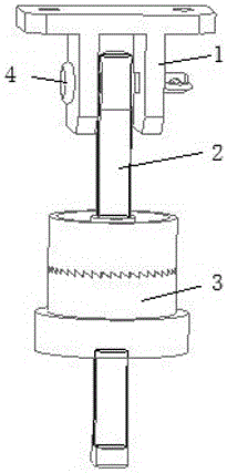
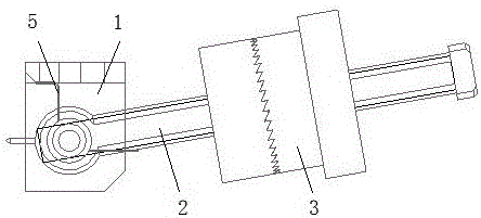
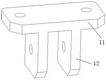
[0022] Specific embodiment 1 of the locking device of the present invention, such as Figure 2 to Figure 5 As shown, the locking device includes a hinge base 1, a connecting rod 2, a locking knob 3, a pin shaft 4 and a torsion spring 5, wherein the axis of the pin shaft 4 extends along the left and right directions, and the hinge base 1 includes a top plate 11 and a fixed The two ear plates 12 on the lower side of the top plate are correspondingly provided with perforations for the pin shaft 4 to wear; in this embodiment, the torsion spring 5 is a double torsion spring structure, and the torsion spring 5 includes a first spring body 50, The second spring body 51, the first connecting rod that one end links to each other with the first spring body, the second connecting rod that one end links to each other with the second spring body, and the U-shaped bar...


PUM


Abstract

The invention relates to a locker. The locker comprises a hinge base, a connecting rod and a torsion spring. The front end of the connecting rod is hinged to the hinge base through a hinge shaft. The torsion spring is arranged at the position, between the hinge base and the connecting rod, of the hinge shaft and used for supporting the connecting rod when the locker is in a non-locking state, the connecting rod is prevented from swinging to the lowest position, the connecting rod is made to stay between the locking position and the lowest position, and accordingly the situation that the connecting rod and a locking rotary knob swing to the lowest position through the gravity and collide with lower-layer equipment in an equipment cabin is avoided; and meanwhile, the swinging angle of the connecting rod is reduced, the operation time is shortened, and the operation efficiency is improved.

Description

technical field [0001] The invention relates to a connecting piece, in particular to a locking device. Background technique [0002] The avionics equipment in the aviation field is generally installed on the equipment bracket during use. In order to make it have a certain impact resistance and vibration resistance, it is often reinforced by corresponding components. The lock is currently the most Common parts used to secure this device. [0003] Such as figure 1 As shown, the locking device includes a hinge base 1, a connecting rod 2 and a locking knob 3. When the locking device is in use, the hinge base 1 is fixed at a corresponding position in the equipment compartment, and the front end of the connecting rod 2 is connected with the pin shaft 4. The hinge base 1 is hinged, wherein the axis of the pin shaft 4 extends along the left and right directions; the connecting rod 2 has a threaded section, and the locking knob 3 is installed at the threaded section of the connecti...

Claims


Application Information

Patent Timeline
Patent Type & Authority Applications(China)
IPC IPC(8): F16C11/04F16C11/10
CPCF16C11/04F16C11/10F16C2326/43
Inventor 徐飞孙亚辉卞军振戚方柱
Owner CHINA AVIATION OPTICAL-ELECTRICAL TECH CO LTD
Why Eureka
Try Eureka