A device and control method
A technology for controlling components and electronic devices, applied in the field of electronics, can solve the problems of high production cost, low cost performance, low function, etc., and achieve the effects of improving the scope of application, improving the applicability, and expanding the range of options.
- Summary
- Abstract
- Description
- Claims
- Application Information
AI Technical Summary
Problems solved by technology
Method used
Image
Examples
Embodiment 1
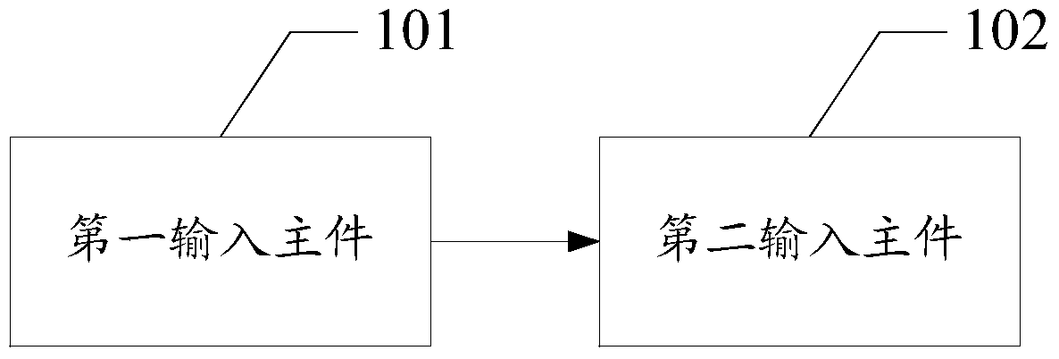
[0060] Please refer to figure 1 , Embodiment 1 of the present application provides an operating device, including:
[0061] The first input main part 101 is arranged on the main body of the operation device, and is used to make the electronic device locate the touch position of the operation device when in contact with the first acquisition component of the electronic device;
[0062] The second input main part 102 is arranged on the main body, and is used for sending a vibration signal for the second collection component on the electronic device to collect when the first input main part is in contact with the first collection component .
[0063] In actual operation, the operating device may be a stylus, a touch stick, or any item that can generate a response command to control the electronic device when in contact with the touch device of the electronic device.
[0064] The first input main part can be the nose tip of the stylus, the head of the touch rod, and any item tha...
Embodiment 2
[0099] Please refer to figure 2 , Embodiment 2 of the present application provides an electronic device, including:
[0100] The first acquisition component 201 is configured to locate a touch position of an operating device when in contact with the operating device;
[0101] The second acquisition component 202 is configured to receive the vibration signal sent by the operating device;
[0102] The processor 203 is configured to determine a first operating mode of the electronic device based on the vibration signal, and control the electronic device to operate in the first operating mode.
Embodiment 3
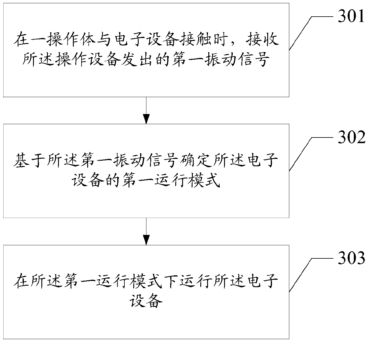
[0104] Please refer to image 3 , Embodiment 3 of the present application provides a control method, including:
[0105] Step 301: Receive a first vibration signal sent by the operating device when an operating body is in contact with the electronic device;
[0106] Step 302: Determine a first operating mode of the electronic device based on the first vibration signal;
[0107] Step 303: Run the electronic device in the first running mode.
[0108] Further, the first operation mode is specifically:
[0109] A mode of displaying a first trajectory with a first color and / or a first line type, wherein the first trajectory is a corresponding one displayed by the electronic device when the electronic device is operated by touch with the operating body. traces of.
[0110] Further, the first operation mode is specifically:
[0111] A mode of displaying the first background; and / or, a mode of playing the first music.
[0112] Further, after step 301, the method further includes...
PUM
 Abstract
Description
Claims
Application Information
 - R&D
- Intellectual Property
- Life Sciences
- Materials
- Tech Scout
- Unparalleled Data Quality
- Higher Quality Content
- 60% Fewer Hallucinations
Browse by: Latest US Patents, China's latest patents, Technical Efficacy Thesaurus, Application Domain, Technology Topic, Popular Technical Reports.
© 2025 PatSnap. All rights reserved.Legal|Privacy policy|Modern Slavery Act Transparency Statement|Sitemap|About US| Contact US: help@patsnap.com


