
Dustproof electric cabinet

A power cabinet and dustproof technology, applied in the field of power cabinets, can solve problems such as damage to power components of power cabinets, and achieve the effect of extending service life, compact structure, and isolating rainwater and dust.

Active Publication Date: 2017-01-11
TIANYUAN HUAWEI GRP
View PDF6 Cites 22 Cited by
  • Summary
  • Abstract
  • Description
  • Claims
  • Application Information

AI Technical Summary

Problems solved by technology

[0002] The power cabinet is a commonly used basic power equipment, which is equipped with a large number of power components; when the power cabinet is working, a large amount of heat is generated inside, therefore, the side wall of the power cabinet needs to be equipped with heat dissipation windows; Strip-shaped shutters, that is, a group of parallel strip-shaped holes are opened on each side wall, and the upper part of each strip-shaped hole has a strip-shaped eaves that are folded down and half surround the strip-shaped holes. Because the strip-shaped holes are used to block rainwater; although the strip-shaped windows are used to block rainwater by the strip-shaped eaves, the dust cannot be blocked by the strip-shaped eaves, and the dust is usually raised from the ground; therefore, it is very It is easy to enter the surrounding area of ​​the strip-shaped eaves, and then enter the strip-shaped holes; it can be considered that the setting of the strip-shaped eaves is more convenient for dust to enter the power cabinet; it will cause greater damage to the power components inside the power cabinet

Method used


Image

  • Dustproof electric cabinet

Examples


Embodiment

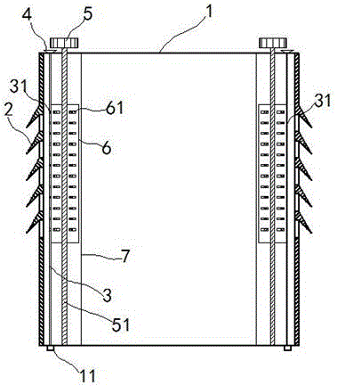
[0016] exist figure 1 In the shown embodiment, the dust-proof power cabinet includes a casing 1, and a heat dissipation window 2 is opened on the side wall of the casing 1. The heat dissipation window 2 includes strip-shaped holes arranged in parallel, and each strip The upper part of the shaped hole has a strip-shaped eaves that are folded down and half surround the strip-shaped hole;

[0017] Inside the housing 1 is provided with a vertical dust-proof net 3, each of the dust-proof nets 3 is close to the side wall with the heat dissipation window 2; a water collecting bucket is arranged on the top of the housing 1 4. The upper edge of the dust-proof net 3 protrudes from the top of the housing 1 and is connected to the bottom of the water collecting bucket 4; a dust discharge groove 11 is provided at the bottom of the housing 1, and the dust-proof net 3 The lower edge protrudes from the dust discharge groove 11;

[0018] Inside the housing 1 is also provided with a vertical ...


PUM


Abstract

The invention relates to a dustproof electric cabinet. The dustproof electric cabinet comprises a shell. Heat dissipation windows are formed in the sidewalls of the shell, and vertical dust screens are arranged in the shell and closely to the sidewalls. A water collecting hopper is arranged at the top of the shell, and the upper edges of the dust screens extend out of the top of the shell and are communicated with the bottom of the water collecting hopper. Dust discharge grooves are arranged at the bottom of the shell, and the lower edges of the dust screens extend out of the dust discharge grooves. Vertical driving shafts are arranged in the shell, the upper ends of the driving shafts penetrate through the top of the shell, and driving fans are fixedly mounted at the upper ends of the driving shafts. Friction plates are mounted on the side circumferential walls of the driving shafts, and the ends of the friction plates are in contact with the dust screens. The dustproof electric cabinet is capable of preventing dust efficiently on the premise of guaranteeing ventilation and heat dissipation, so that cleanliness and safety can be improved effectively and interior electric elements can be better protected.

Description

technical field [0001] The invention relates to a power device, in particular to a power cabinet. Background technique [0002] The power cabinet is a commonly used basic power equipment, which is equipped with a large number of power components; when the power cabinet is working, a large amount of heat is generated inside, therefore, the side wall of the power cabinet needs to be equipped with heat dissipation windows; Strip-shaped shutters, that is, a group of parallel strip-shaped holes are opened on each side wall, and the upper part of each strip-shaped hole has a strip-shaped eaves that are folded down and half surround the strip-shaped holes. Because the strip-shaped holes are used to block rainwater; although the strip-shaped windows are used to block rainwater by the strip-shaped eaves, the dust cannot be blocked by the strip-shaped eaves, and the dust is usually raised from the ground; therefore, it is very It is easy to enter the surrounding area of ​​the strip...

Claims


Application Information

Patent Timeline
Patent Type & Authority Applications(China)
IPC IPC(8): H02B1/28H02B1/30
CPCH02B1/28H02B1/30
Inventor 仲炳华
Owner TIANYUAN HUAWEI GRP
Learn More