Optical coupling touch switch

A technology of touch switch and optical coupling, which is applied in the field of optical coupling touch switch, can solve the problems of easy damage of mechanical switches, achieve long service life and solve the effect of easy damage of mechanical wear

Inactive Publication Date: 2017-01-11
CHENGDU CYLON ELECTRONICS TECH
View PDF0 Cites 0 Cited by
  • Summary
  • Abstract
  • Description
  • Claims
  • Application Information

AI Technical Summary

Problems solved by technology

[0003] The purpose of the present invention is to overcome the defect that the current mechanical switch is easily damaged, and to provide an optically coupled touch switch

Method used


Image

  • Optical coupling touch switch

Examples


Embodiment

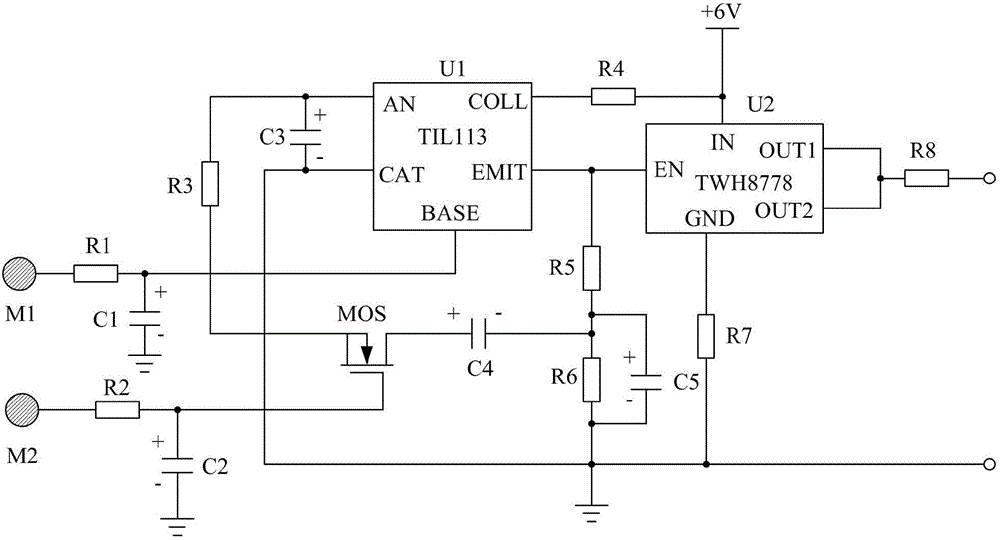
[0012] Such as figure 1 As shown, the present invention mainly consists of an optical coupling chip U1, a current switch chip U2, a field effect transistor MOS, a touch panel M1, a touch panel M2, a resistor R1, a resistor R2, a resistor R3, a resistor R4, a resistor R5, a resistor R6, and a resistor R7 , a resistor R8, a capacitor C1, a capacitor C2, a capacitor C3, a capacitor C4 and a capacitor C5.

[0013] Among them, the resistor R1 and the capacitor C1 form the first RC filter; one end of the resistor R1 is connected to the touch chip M1, and the other end is connected to the BASE pin of the optical coupling chip U1; the positive electrode of the capacitor C1 is connected to the BASE pin of the optical coupling chip U1 BASE pins are connected, and the negative pole is grounded.

[0014] Resistor R2 and capacitor C2 form a second RC filter; one end of the resistor R2 is connected to the touch panel M2, and the other end is connected to the gate of the field effect transi...


PUM


Abstract

The invention discloses an optical coupling touch switch. The optical coupling touch switch is characterized by being mainly composed of an optical coupling chip U1, a current switch chip U2 and the like. According to the optical coupling touch switch, a human body only needs to touch different touch chips, an illuminating lamp can be turned on or turned off, and compared with a traditional mechanical switch, the optical coupling touch switch has the advantages that no mechanical wear is generated, the service life is longer, and the problem that the mechanical switch is prone to be damaged due to mechanical wear is effectively solved.

Description

technical field [0001] The invention relates to a touch switch, in particular to an optical coupling touch switch. Background technique [0002] At present, household lighting lamps are usually controlled by a mechanical switch, and the power supply of the lighting lamp is controlled to be turned on and off by controlling the conduction and closing of the mechanical switch. However, in the process of using the mechanical switch, it is very easy to be damaged due to repeated operation, which causes great mechanical wear and tear, which brings great troubles to people. Contents of the invention [0003] The purpose of the present invention is to overcome the defect that the current mechanical switch is easily damaged, and provide an optical coupling touch switch. [0004] The object of the present invention is achieved through the following technical solutions: an optical coupling touch switch mainly consists of an optical coupling chip U1, a current switch chip U2, a field...

Claims


Application Information

Patent Timeline
Patent Type & Authority Applications(China)
IPC IPC(8): H03K17/96H03K17/16H05B33/08H05B44/00
CPCH03K17/161H03K17/96H05B45/40
Inventor 梁毅俞德军
Owner CHENGDU CYLON ELECTRONICS TECH
Why Eureka
Try Eureka