Rotary regulation mechanism of hydraulic lifting seat

A rotary adjustment, hydraulic lifting technology, applied in vehicle seats, movable seats, special positions of vehicles, etc., can solve the problems of reduced effective use area, no locking mechanism for lift seats, and narrow use space.

Active Publication Date: 2017-01-18
富士房车(江苏)有限公司
View PDF5 Cites 2 Cited by
  • Summary
  • Abstract
  • Description
  • Claims
  • Application Information

AI Technical Summary

Problems solved by technology

[0002] In passenger cars, it is often necessary to set up parts such as seats to meet the requirements of meeting and resting in commercial vehicles. However, as we all know, due to the limited space of passenger cars, the structural installation of each component will bring a relatively large impact on the overall space. Therefore, in passenger cars, the three-dimensional space is usually effectively used through changes in various aspects of the layout pattern. For the seat installation in passenger cars, in order to meet the needs of lifting and rotating adjustments, usually through Set the fixed rotating shaft to rotate on the plane to achieve the purpose of multi-purpose. However, in many cars, because the plane rotation interferes with the surrounding doors, hand brakes, and brake handles, it cannot be rotated more than 90 degrees. It is necessary to set up a complex mechanism to realize it. Therefore, the passenger car with limited vehicle space is equipped with such a complex adjustment structure, which makes the use space narrower, the effective use area is also greatly reduced, and the comfort requirements are lowered. In addition, the existing lifting seat does not have a reliable locking mechanism, so its safety is difficult to be guaranteed

Method used


Image

  • Rotary regulation mechanism of hydraulic lifting seat

Examples


Embodiment Construction

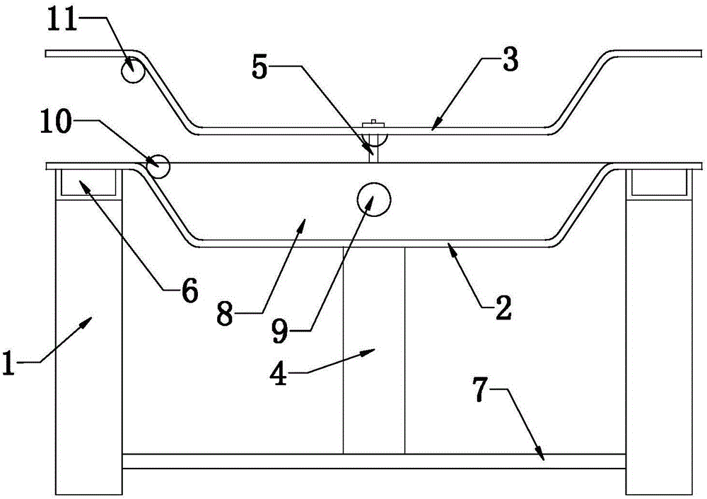
[0014] The rotary adjustment mechanism of the hydraulic lifting seat of the present invention will be described in further detail below in conjunction with the accompanying drawings and specific embodiments.

[0015] As shown in the figure, the hydraulic lift seat rotation adjustment mechanism of the present invention includes a seat frame 1, a mounting base 2 arranged on the seat frame 1 and a seat base 3 located above the mounting base, and the bottom of the mounting base 2 is arranged There is a cylinder block 4 between the seat brackets, said cylinder block 4 is an air cylinder block or a hydraulic cylinder block, preferably a hydraulic cylinder, and the telescopic rod 5 in the cylinder block 4 stretches out from the top of the mounting base 2 and is connected to the seat The bottom of the chair base, the seat base 2 can rotate around the center of the telescopic rod after the telescopic rod stretches out.

[0016] It can be seen from the figure that the seat frame include...


PUM


Abstract

The invention discloses a rotary regulation mechanism of a hydraulic lifting seat. The rotary regulation mechanism comprises a seat bracket, an installation base and a seat base, wherein the installation base is arranged on the seat bracket; the seat base is installed above the installation base; the bottom of the installation base is provided with a cylinder positioned between the seat bracket; an expansion link in the cylinder extends to be above the installation base and is connected to the bottom of the seat base; the seat base can rotate around the center of the expansion link after the expansion link is extended. After the above structure is adopted, the seat can be lifted through a hydraulic cylinder or an air cylinder to realize the purpose of a multifunctional seat, and meet the requirements of height lifting and seat angle regulation; a guide slot and rail cooperation structure is cooperated with a pulling handle to carry out front and back regulation on the seat, regulation is convenient and reliable, locking is reliable through the design of a push-pull plate and a locking structure on the push-pull plate, and reliability and safety in use are guaranteed. The rotary regulation mechanism has the advantages of artful and reasonable structure design, convenience in regulation and use and small land occupation, and therefore, the comfort level of a whole passenger car is greatly improved.

Description

technical field [0001] The invention relates to an accessory of a vehicle and a passenger car, in particular to a hydraulic lift seat rotation adjustment mechanism. Background technique [0002] In passenger cars, it is often necessary to set up parts such as seats to meet the requirements of meeting and resting in commercial vehicles. However, as we all know, due to the limited space of passenger cars, the structural installation of each component will bring a relatively large impact on the overall space. Therefore, in passenger cars, the three-dimensional space is usually effectively used through changes in various aspects of the layout pattern. For the seat installation in passenger cars, in order to meet the needs of lifting and rotating adjustments, usually through Set the fixed rotating shaft to rotate on the plane to achieve the purpose of multi-purpose. However, in many cars, because the plane rotation interferes with the surrounding doors, hand brakes, and brake han...

Claims


Application Information

Patent Timeline
IPC IPC(8): B60N2/14B60N2/16
CPCB60N2/14B60N2/16B60N2/1665
Inventor 江村龙一
Owner 富士房车(江苏)有限公司
Why Eureka
Try Eureka