Rotary display platform and rotary display equipment
A technology of pan/tilt and rotating parts, which is applied in the field of display equipment, and can solve the problems of poor panoramic display effect, inability to display products and photograph products at precise angles, etc.
- Summary
- Abstract
- Description
- Claims
- Application Information
AI Technical Summary
Problems solved by technology
Method used
Image

Examples
no. 1 example
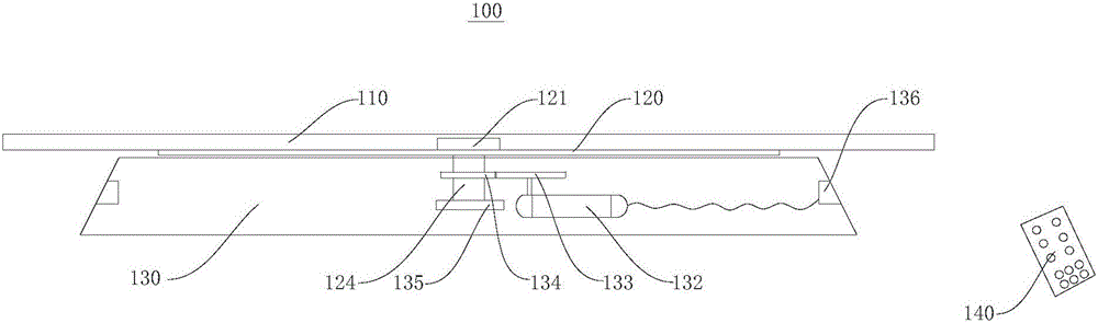
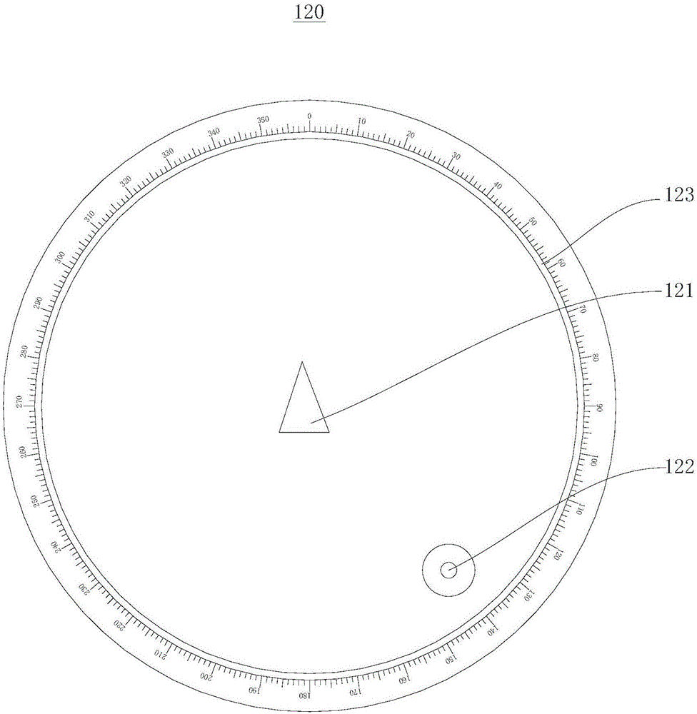
[0031] Please refer to figure 1 , the present embodiment provides a rotating display device 100, which is used to place the products to be displayed and rotate the products to be displayed, so as to display the products to be displayed in an all-round and accurate manner, and facilitate shooting. The rotating display device 100 includes a display table 110 , a rotating member 120 and a base 130 .
[0032] The display table 110 is used to support and display the products to be exhibited, and the display table 110 can rotate under the drive of the rotating member 120 , thereby driving the rotation of the products to be displayed on the display table 110 . The shape and size of the display table 110 can have multiple options, and can be selected according to the size of different products to be displayed. In this embodiment, the display table 110 is circular with a diameter of 60 cm and a thickness of 1 cm. In other embodiments, the diameter and thickness of the display table 1...
no. 2 example
[0054] Please refer to Figure 5 , this embodiment provides a rotating display device 200 , which is substantially the same as the rotating display device 100 of the first embodiment, the difference between the two is that the rotating display device 200 of this embodiment further includes a locking mechanism 250 . The locking mechanism 250 is disposed in the base 130 and is used to limit the rotation of the rotating member 120 and prevent the rotating member 120 from rotating unexpectedly due to external force.
[0055] The locking mechanism 250 includes an electromagnet 251 and a metal rod 252, a spring 253 is connected in the electromagnet 251, and the other end of the spring 253 is connected with the metal rod 252, and the top surface of the base 130 is provided with a hole for the metal rod 252 to pass through. Through holes (not shown), the end of the metal rod 252 away from the spring 253 selectively passes through and abuts against the bottom surface of the rotating me...
no. 3 example
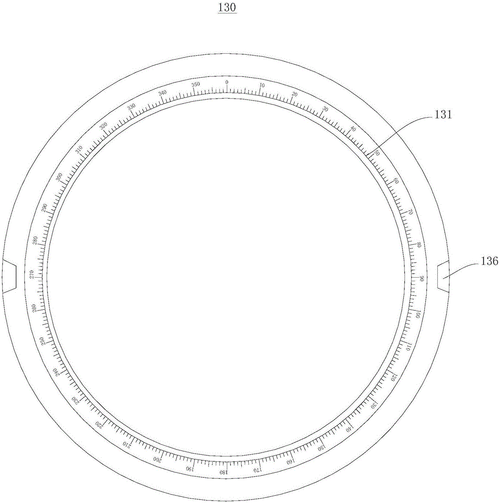
[0061] Please refer to Image 6 with Figure 7 , this embodiment provides a rotating display device 300, which is substantially the same as the rotating display device 100 of the first embodiment, the difference between the two is that the scale in the rotating display device 300 of this embodiment is a pointer 325, and the first moment The dial 131 is provided with a plurality of wire grooves 328, and the wire grooves 328 are recessed in the first dial 131 to form an angle scale, and the pointer 325 includes an indicating segment 326 and a positioning segment 327, and the indicating segment 326 and the positioning segment 327 are connected to each other And form an "L" shape, the indicating segment 326 is located on the top surface of the rotating member 120, and the end of the positioning segment 327 away from the indicating segment 326 is rotatably embedded in the wire groove 328, when the rotating member 120 rotates relative to the base 130 , the positioning section 327 o...
PUM
| Property | Measurement | Unit |
|---|---|---|
| Thickness | aaaaa | aaaaa |
| Diameter | aaaaa | aaaaa |
| Height | aaaaa | aaaaa |
Abstract
Description
Claims
Application Information
 - R&D
- Intellectual Property
- Life Sciences
- Materials
- Tech Scout
- Unparalleled Data Quality
- Higher Quality Content
- 60% Fewer Hallucinations
Browse by: Latest US Patents, China's latest patents, Technical Efficacy Thesaurus, Application Domain, Technology Topic, Popular Technical Reports.
© 2025 PatSnap. All rights reserved.Legal|Privacy policy|Modern Slavery Act Transparency Statement|Sitemap|About US| Contact US: help@patsnap.com