
Grease smearing device for piston pin holes
A piston pin hole and grease coating technology, which is applied to the device and coating of the surface coating liquid, can solve the problems of not being able to meet the production scale, achieve the effects of reasonable structural design, improve coating efficiency, and save manpower and material resources
- Summary
- Abstract
- Description
- Claims
- Application Information
AI Technical Summary
Problems solved by technology
Method used
Image

Examples
Embodiment Construction
[0015] In order to make the technical means, creative features, goals and effects achieved by the present invention easy to understand, the present invention will be further elaborated below.
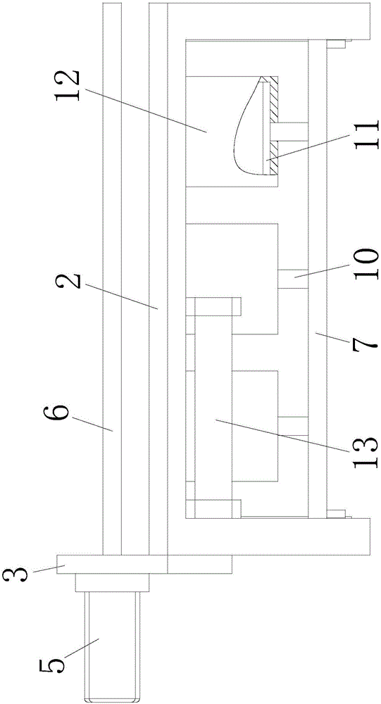
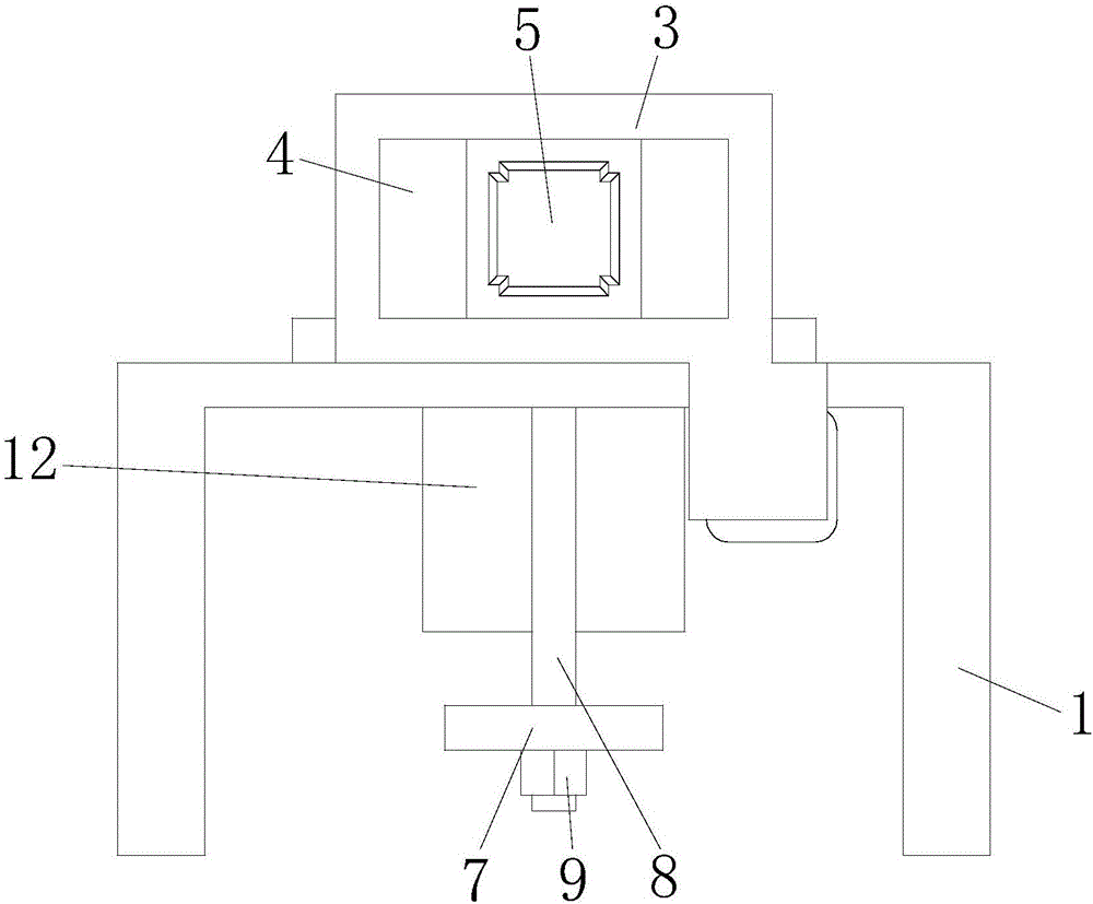
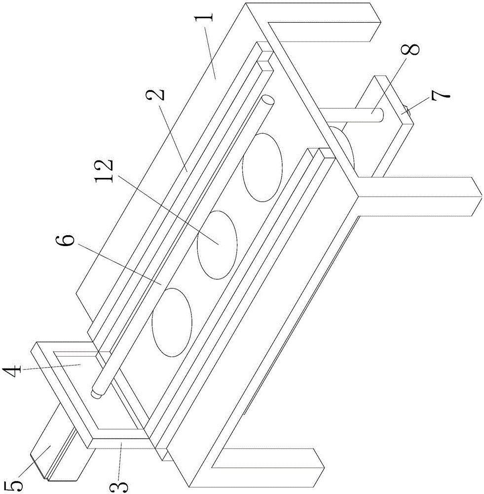
[0016] Such as Figure 1 to Figure 3 As shown, a grease coating device for a piston pin hole includes a support table 1, the upper end of the support table 1 is equipped with a slide rail 2 arranged laterally, and a slide frame 3 is installed on the slide rail 2, and the slide rail 2 is mounted on the slide rail 2. A mounting plate 4 is fixed on the frame 3, and a motor 5 arranged laterally is fixed on the left end of the mounting plate 4, and a smearing wheel 6 is installed on the shaft of the motor 5. When in use, the motor 5 works to drive the smearing wheel 6 to rotate to smear the pin hole of the piston, so as to provide necessary conditions for the work of the device.
[0017] The bottom of the support platform 1 is provided with a connecting plate 7, and the left and right parts...
PUM
 Abstract
Description
Claims
Application Information