Rigid wall air-supported axis compression rod piece

An axial compression and rod technology, which is applied in the direction of construction and building structure, can solve the problems of restricting the application of high-strength materials and cannot transmit pressure well, achieve good market application prospects, and improve overall and local stability. The effect of increasing the speed of construction

Active Publication Date: 2017-01-25
NORTHWESTERN POLYTECHNICAL UNIV
View PDF6 Cites 1 Cited by
  • Summary
  • Abstract
  • Description
  • Claims
  • Application Information

AI Technical Summary

Problems solved by technology

Due to the limitation of the slenderness ratio, the compression members cannot transmit the pressure of a long distance well. In addition, this also limits the application of high-strength materials in the space grid structure

Method used


Image

  • Rigid wall air-supported axis compression rod piece
  • Rigid wall air-supported axis compression rod piece
  • Rigid wall air-supported axis compression rod piece

Examples


Embodiment Construction

[0028] The present invention will now be further described in conjunction with the embodiments and drawings:

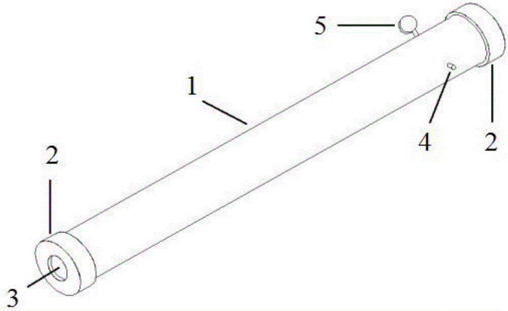
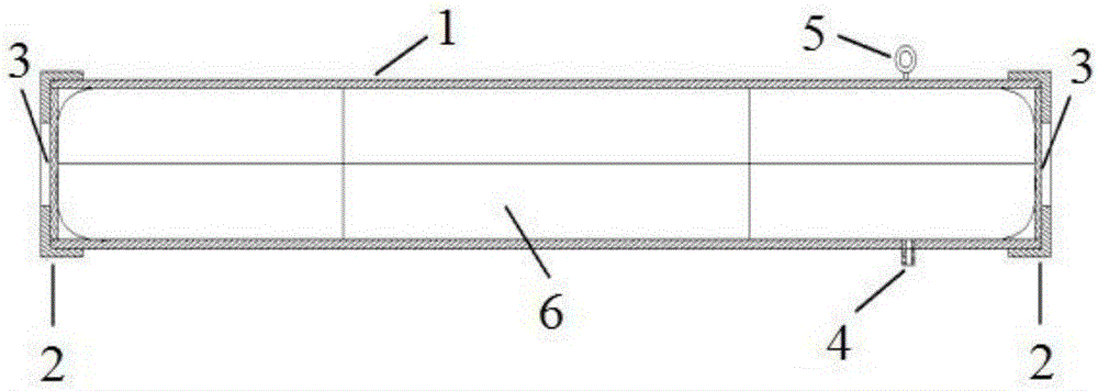
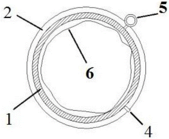
[0029] See the three-dimensional diagram of the compression rod of rigid wall air bearing shaft figure 1 , Including rigid pipe 1 (see Figure 4 ), airbag 2 (see Figure 5 ), barometer 3, holding plate 4 (see Image 6 ), screw cap 5 (see Figure 7 ). The specific arrangement is to place the airbag 2 longitudinally along the axial direction of the rigid tube 1 so that the position of the airbag inflation valve corresponds to the position of the reserved inflation hole of the rigid tube 1 and fix the inflation valve. The barometer 3 is installed on the reserved tube wall of the rigid tube. Next to the connecting hole and communicate with the airbag, two holding plates 4 are respectively placed at the two ends of the rigid tube 1, and then the two screw caps 5 are tightly connected with the two ends of the rigid tube 1 through threads.

[0030] The rigid tube is a hollow roun...


PUM


Abstract

The invention relates to a rigid wall air-supported axis compression rod piece. The rigid wall air-supported axis compression rod piece comprises a rigid pipe, an air bag, an air pressure gauge, force maintaining plates and thread caps; an air bag inflating hole and an air pressure gauge communicating hole are reserved in the pipe wall of the rigid pipe; the air bag is placed in the axial direction of the interior of the rigid pipe; the air pressure gauge is mounted at the communicating hole which is reserved in the pipe wall of the rigid pipe and is communicated with the air bag; the force maintaining plates are positioned at the two ends of the air bag and are internally tangent to the inner wall of the rigid pipe; the thread caps are respectively in threaded connection with the two ends of the rigid pipe. When the rigid wall air-supported axis compression rod piece is in a normal working state, the rigid wall of the rod piece does not bear pressure; the axial pressure is completely borne through the air bag, and is converted into circumferential tensile stress of the rigid wall, so that the axial compressive bearing capacity of the rod piece is improved, and the tensile strength of a rigid wall material can be fully utilized to achieve the purposes of light weight and high strength. The rigid wall air-supported axis compression rod piece is simple in structural form, safe and economical, and has a good market application prospect.

Description

Technical field [0001] The invention belongs to the field of components in engineering structures, and specifically relates to a rigid-wall air-bearing shaft-centered compression rod. Background technique [0002] Spatial grid structures such as grids and reticulated shells are widely used in stadiums, railway stations, terminal buildings and some special structures. The spatial grid structure is composed of rigid rods of different lengths combined according to a certain topological relationship. Generally, the rods in the structure are mainly subjected to axial force. When hinged nodes are used, the members only bear the axial force. For tension members, high-strength materials can be used to increase the tensile bearing capacity of the members, while the bearing capacity of the compression members is controlled by stability, and the material strength has no effect on the bearing capacity of the compression members. Big. Limited by the slenderness ratio, the compressed bar ca...

Claims


Application Information

Patent Timeline
Patent Type & Authority Applications(China)
IPC IPC(8): E04B1/24
CPCE04B1/24E04B2001/2466
Inventor 李玉刚张玉强连业达
Owner NORTHWESTERN POLYTECHNICAL UNIV
Why Eureka
Try Eureka