A direction-changing drill pipe power transmission device

A technology of power transmission device and drill pipe, which is applied in the direction of drilling equipment, earthwork drilling, drilling equipment and methods, etc., and can solve the problem of inability to realize the drill pipe and grouting pipe changing direction drilling and grouting, and the inability to use underground depth drilling Holes, inability to complete drilling and grouting, etc., to achieve the effect of low comprehensive construction cost, significant social benefits, and small traffic impact range

Active Publication Date: 2017-07-21
HEFEI UNIV OF TECH
View PDF6 Cites 0 Cited by
  • Summary
  • Abstract
  • Description
  • Claims
  • Application Information

AI Technical Summary

Problems solved by technology

It can be seen that the current drilling and grouting technology has the following deficiencies: First, the drill pipe and grouting pipe of the polymer grouting technology are long straight pipes, which cannot bypass the existing road foundation at a certain depth underground at a certain angle. and building foundation etc. to change direction, also can not realize the drill pipe and grouting pipe to change direction drilling grouting; the second is in the reinforcement method of building foundation, usually the diameter of grouting pipe is 25mm, and the inclination angle with the horizontal plane is not the same. If it is less than 30°, it is impossible to complete drilling and grouting at any depth; third, although the horizontal directional drilling machine has realized the turning and changing direction of the drilling, its drilling arc is limited and the radius of curvature is very large. At the same time, the deeper the drilling, the deeper the radius of curvature In addition, the specified entry and exit angle, curvature radius, drill pipe material strength and geological conditions are limited, so it cannot be used for deep underground drilling, otherwise the construction will be extremely difficult

Method used


Image

  • A direction-changing drill pipe power transmission device
  • A direction-changing drill pipe power transmission device
  • A direction-changing drill pipe power transmission device

Examples


Embodiment Construction

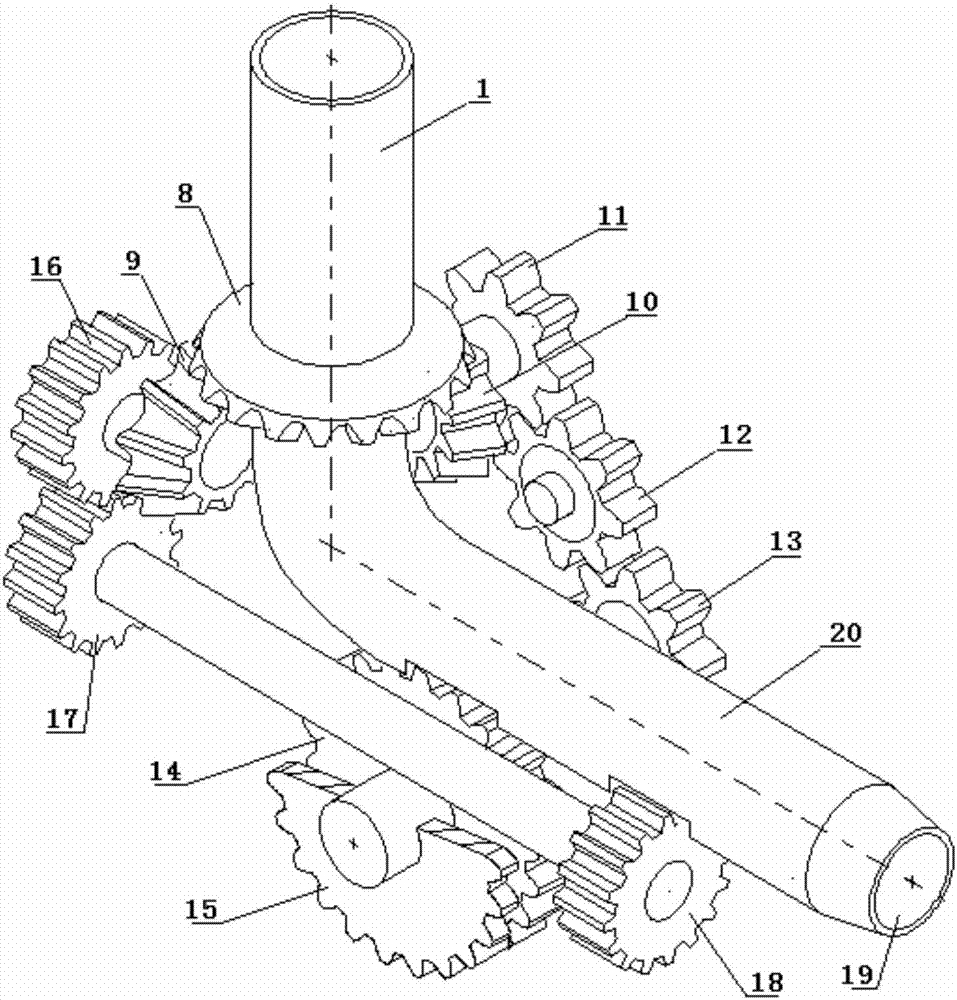
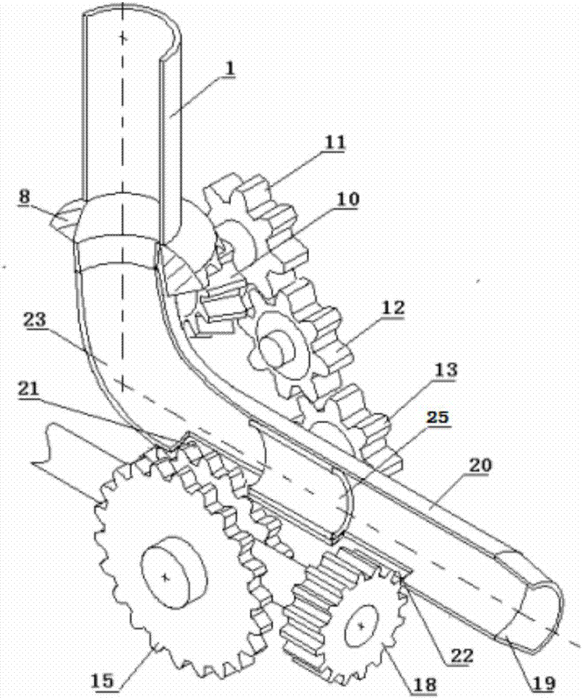
[0029] see figure 1 , figure 2 , image 3 , Fig. 4a, Fig. 4b and Fig. 4c, the power transmission device of the reversing drill pipe in this embodiment includes: a drill pipe channel, an assembled drill pipe and a transmission mechanism.

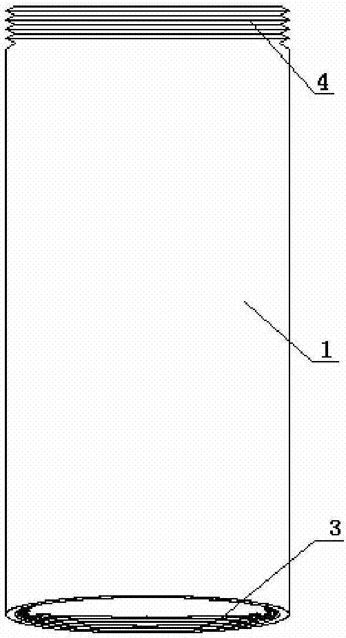
[0030] The drill pipe channel is the inlet pipe of the drill pipe with a section of vertical straight pipe 1, a section of straight pipe arranged in a set direction as the guide track 20, and the front end of the guide track is the track outlet 19, between the vertical straight pipe 1 and The guide rails 20 are smoothly transitioned and connected by an arc track 23 to form a through drill pipe channel with steering. The arc track 23 is used to realize the direction change of the drill pipe track. The turning angle should be greater than 90°; the vertical straight pipe 1 in the drill pipe channel is set as a rotatable pipe, and the motor provides driving force for the vertical straight pipe 1; the assembled drill pipe is composed of at leas...


PUM


Abstract

The invention discloses a power transferring device of a turning drilling rod. The power transferring device is characterized by comprising a drilling rod channel, an assembly type drilling rod and a transmission mechanism, wherein the drilling rod channel comprises a vertical straight tube which is used as an inlet tube of the drilling rod and a straight tube which is used as a guide rail in a preset direction, and the vertical straight tube is in smooth transition connection with the guide rail through an arc track so as to form the turning and penetrating drilling rod channel; the vertical straight tube can rotate, and driving force is supplied to the vertical straight tube by a motor; the assembly type drilling rod is in threaded connection between adjacent drilling rod sections; transmission gears are distributed in arrays on the outer circumferential surfaces of the drilling rod sections, and driving force is supplied to the transmission gears by utilizing the transmission mechanism. According to the power transferring device, the drilling direction of the drilling rod is changed at a large angle, turning transmission of the drilling rod is realized, and the problem of bypassing obstacles in the drilling process of the drilling rod can be effectively solved.

Description

technical field [0001] The invention relates to a direction-changing drill pipe drilling and grouting pipeline device, more specifically a power transmission device for a direction-changing drill pipe. Background technique [0002] Drilling and grouting technology is a commonly used technology in civil engineering and geotechnical engineering, which can be applied to foundation construction and foundation reinforcement. [0003] At present, grouting technology is mainly used in foundation pit support, seepage prevention and plugging, and foundation reinforcement in geotechnical engineering. The grouting method is to inject curable grout into cracks or pores in rock foundations to improve its Construction methods of physical and mechanical properties. In recent years, the grouting method represented by polymer grouting technology has been widely used in the field of road and construction engineering. The key steps in the construction process are drilling and grouting. The gr...

Claims


Application Information

Patent Timeline
Patent Type & Authority Patents(China)
IPC IPC(8): E21B7/08
CPCE21B7/067
Inventor 董满生郝艳海汪忠明鹿立好
Owner HEFEI UNIV OF TECH
Why Eureka
Try Eureka